
Specifications

Peripherals
©2002 Bally Gaming and Systems 8-15
Peripherals
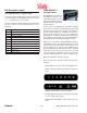
Bill Acceptors (cont.)
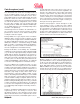
• Insert a known bill/note.
• The bill/note will either go completely though, or be
rejected.
• If the bill/note rejects, check calibration. Recalibrate
if necessary. If the unit still rejects, there is a possible
sensor problem, or incorrect software version. See
Bill Return Codes.
• If the acceptor does not take the bill/note, check for
power.
• When the unit cycles on power ON, this indicates
power and forward motor operation.
• When a plain piece of paper is inserted and rejected,
this indicates reverse motor operation.
• When various denominations of bills are inserted and
accepted, this indicates the bill was successfully
matched against the characteristics of the software.
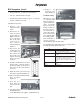
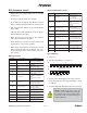
Bill Return Codes
NOTE: Verification that the unit is function
properly can be done while in test mode.
NOTE: Recalibration is required after
installation of a new CPU.
NOTE: Calibration paper may be
purchased from JCM American directly
by calling the Parts Sales department at
(702) 651-3445 and requesting part
number #501-000032.
sknilBfo# noitpircseD esuaCelbissoP
1
noitresnidekoorC
ro1TProsnes31,21,11,01-ABW
gnikrowton2TP
ro3TProsnes32,22,12,02-ABW
gnikrowton4TP
dekoorcdetresnilliB
22
2
22
rorrenrettapcitengaM
stleb/srellorytriD
BCProsnesgamdaB
33
3
33
dessapybsrosnesecnartnE
ro2TPdna1TPnahtrehtorosneS
f
oecneserpehtdetceted4TPdna3TP
ybdnatsnielihweton/llibeht
4
ehtwolebsioitarthgil-kraD
eulavdexif
gnikrowebtonyamsrosnesevitcelfeR
55
5
55
detcetedtonlliB
rosnesaybdetcetedtoneton/lliB
doirepdeificepsanihtiw
rosnesnideefroRPH,LPH,CPH
77
7
77
rorrerosnesotohP
tonnrettapaevahyameton/lliB
yromemnidezingocerrodemmargorp
88
8
88
rorrelevelotohP
ytridebyametonllibehT
detcetedseton/llibgnippalrevO
99
9
99
eton/lliblagellI
ehtotnillaftonseodeton/llibehT
niseton/llibelbatpeccafoegnar
margorp
1111
11
1111
smelborplevelrekcatS
gnikrowtondioneloS
ehtfonoitisopwonktonyamrosneS
revelrekcats
2121
21
2121
rorregnimiT
ehtneewtebdedargedsignimitehT
eton/llibehtkcarttahtsrosnes
tnemevom
3131
31
3131
rorrehtgneletoN/lliB
nrotsieton/lliB
trohsootsieton/llibnonoitartsigeR
4141
41
4141
rorrenrettaproloC
sieton/llibehtnonrettaproloC
tcerrocni
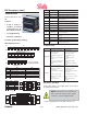
Auto-Calibration - Sensors
Description: Calibration sets a starting reference point for
all optical sensors within the unit. This can be done at the
host unit, or at the work bench with just a power source.
When to Calibrate:
• After the acceptor’s components have been disas-
sembled for repair.
• After a sensor board has been replaced.
• Whenever bill/note acceptance is degraded.
• During scheduled preventative maintenance (see
Module 4, Periodic Maintenance)
• When upgrading/downloading software.
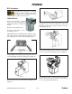
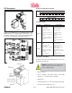
Procedure:
1. Remove transport unit with head.
2. Set DIP switches 5, 6, 7, and 8 to the on position, all
others to the off position.
3. Connect transport unit with head to a power source -
either the host machine, or adaptive power supply.
4. Listen for activation of the transport motor - forward
and reverse for up to two seconds, then stop - READY.
5. After inserting the calibration paper, black paper first,
the unit will carry the paper forward/reverse several
times. When the process is complete, the unit will
return the paper.
6. Wait a few moments to allow for complete transfer of
calibration data to be stored in memory. This is indi-
cated via the LED on the test harness, or the bezel
light on some applications with fast blinks.
7. Unsuccessful calibrations: Check the lenses. Retry
calibration. If necessary, refer to the Error Conditions
table following. Additional testing/troubleshooting may
be required.