
Installation Guide

--------------------------------------------------------------------------------10/32--------------------------------------------------------------------------------
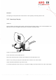
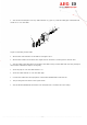
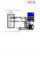
3.3.3.3 Pin assignment of the SAB connectors
Figure 5: Pin assignment of the SAB connectors
RS232
(9 Pins Sub-D female)
1
2
3
4
5
6
7
8
9
RxD (reader)
TxD (reader)
GND
+U
S1
-U
S1
green
ARE I2
shielding
V+ (+24V)
GND (0V)
TXD
RXD
V+
DC
black
+U
S2
-U
S2
B
A
D
C
E