
Installation Guide

--------------------------------------------------------------------------------26/32--------------------------------------------------------------------------------
8.2 Writing WD
The memory of the transponder is organised in blocks, containing 32 bits. The data’s of every single
block must be changed separately.
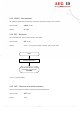
• Start the reader with the command WD plus parameters ( plus <CR>). The sent parameter consists
of the block address and writing data’s (8 ASCII characters).
• Wait for the answer
• Analyse the received answer: 3 characters plus <CR>.
ACK <CR> Writing process was successful
NAK <CR> Writing process was not successful.
NOT <CR> The response of the transponder was not readable.
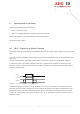
The result of the writing process may also seen at the LED’s.
• LED L2 lit, if there was a successful write
• LED L3 lit, if there was no successful write.
Example: WD <SP> 20 <SP> < 0 1 2 7 A C D F > <CR> write to block 20
Allowed values (block numbers of the transponder IC):
ALGO 9 (1 kBit; P4150, P4450, P4550) 3 ... 33
ALGO 6 (2 kBit; Hitag 1) 16 ... 63
ALGO 14 (2, 4; kBitEM4305, EM4569) 5 … 15