
User Guide

--------------------------------------------------------------------------------4/18--------------------------------------------------------------------------------
1 Introduction
This document will describe the components of the reader system ARE K1 / PFB and the procedure
how to do the set up of the reader. The main features of the reader are listed below:
• algorithms to read Trovan und PSK1-transponders
• the Profibus-DP-interface is opto-isolated and placed inside of the housing, allowed baud rate are
up to 12MBit/s
• the node address of the reader can be chosen from 2 to 99, using adress switches which can be set
without opening the housing
• the allowed supply voltage is 18 to 28VDC (typical 24V)
• The reader is equipped with an galvanic disconnected digital input. The positive edge causes a
trigger signal. The input voltage is 24 V.
• low power consumption of reader < 24Watt
• high reliability for reading within an industrial environment.
• reading distance using the ID 200 transponder and the AAN FK2 antenna:
- 40 cm in static application
- 30 cm when transponder is moved with up to 10m/min
• different antenna types available to meet special application demands
• fully compatible with Compact reader system ARE I2 / PFB
• the cabling concept of the reader is optimised to service demands.
• the protection class of the housing is IP65
• ambient temperatur limit: -20 to 70 °C
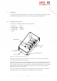
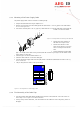
2 System Overview
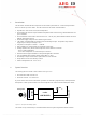
The reading systems consists of two modules (see Figure 2-1)
• the reader box ARE K1/PFB and
• the active antenna (i.e. AAN FK2)
By means of the active antenna the reader generates an alternating magnetic field, which powers the
transponder. Coded signals sent back from the transponder are received and decoded by the reader.
Profibus DP
24V
DC
antenna
transponder
reader
ARE K1/PFB
Figure 2-1: Concept of the Reading System
The reader is fully controlled by an Profibus-Master while using the integrated Profibus interface.