35772 G AUS ERFAHRUNG GUT Gas hob Instruction Booklet GB
Important Safety Information You MUST read these warnings carefully before installing or using the hob. If you need assistance, contact our Customer Care Department on 08705 350350 Installation l This hob must be installed by qualified personnel, according to the manufacturers instructions and to the relevant British Standards. l Any gas installation must be carried out by a registered CORGI installer. l Remove all packaging before using the hob.
l Do not use this hob if it is in contact with water. Do not operate the hob with wet hands. l Ensure the control knobs are in the OFF position when not in use. l l When using other electrical appliances, ensure the cable does not come into contact with the hot surfaces of the cooking appliance. Unstable or misshapen pans should not be used on the hob as unstable pans can cause an accident by tipping or spillage. l Never leave the hob unattended when cooking with oil and fats.
Contents Instructions for the User Important Safety Information Description of the Hob Operation Maintenance and Cleaning Something Not Working? Service and Spare Parts Customer Care Guarantee Conditions 2 5 6 7 8 9 9 10 Instructions for the Installer Engineers technical data Important safety requirements Installation Electrical connections Wiring diagram Fault Finding Commissioning Conversion from Natural Gas to LPG Guide to Use the instructions The following symbols will be found in the text to guide y
Description of the Hob 4 3 1 Fig. 1 5 2 2 6 1. Hob Top 2. Semi-rapid burner 3. Auxiliary burner 4. Rapid burner 5. Ultra-rapid burner 6. Control knobs Installation Any gas installation must be carried out by a registered CORGI installer, and in accordance with existing rules and regulations. The relevant instructions are to be found in the second section of this manual. Please, ensure that, once the hob is installed, it is easily accessible for the engineer in the event of a breakdown.
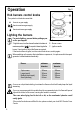
Operation Fig. 2 Hob burners control knobs The symbols on the knobs mean that : l there is no gas supply there is maximum gas supply there is minimum gas supply Lighting the burners F For easier lighting, proceed before putting a pan on the pan support. To light a burner, turn the relevant knob anticlockwise to FO 0204 A - Burner cap B - Burner crown C - Ignition candle maximum position ( ), then push it down to ignite the burner. Upon ignition, adjust the flame as required.
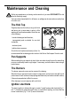
Maintenance and Cleaning Before any maintenance or cleaning can be carried out, you must DISCONNECT the hob from the electricity supply. The hob is best cleaned whilst it is still warm, as spillage can be removed more easily than if it is left to cool. The Hob Top Regularly wipe over the hob top using a soft cloth well wrung out in warm water to which a little washing up liquid has been added.
Something Not Working? If the hob is not working correctly, please carry out the following checks before contacting your local AEG Service Force Centre. SYMPTOM n There is no spark when lighting the gas SOLUTION u u Check that the RCCB has not tripped (if fitted) u Check the mains fuse has not blown u n The gas ring burns unevenly Check that the unit is plugged in and the electrical supply is switched on u u Check the burner cap and crown have been replaced correctly, e.g. after cleaning.
Service and Spare Parts If you require spare parts or an engineer contact your local Service Force Centre by telephoning: 0870 5 929 929 Your call will be routed to the your local Service Force Centre. For the address of your local Service Force Centre and further information about Service Force, please visit the website at www.serviceforce.co.uk 1. 2. 3. 4. 5. When you contact the Service Force Centre, they will need the following information: Your name, address and post code.
Guarantee Conditions AEG offer the following guarantee to the first purchaser of this appliance. 1. The guarantee is valid for 12 months commencing when the appliance is handed over to the first retail purchaser, which must be verified by purchase invoice or similar documentation. The guarantee does not cover commercial use. 2. The guarantee covers all parts or components which fail due to faulty workmanship or faulty materials.
Instruction for the Installer Engineers technical data Overall dimensions Width: Depth: Burner 680 mm. 510 mm. Cut out dimensions Width: Depth: 560 mm. 480 mm. Supply Connections Gas:R 1/2 inch (1/2 inch male) Rear right hand corner Electric: 230-240V 50Hz supply, 3 core flexible cable with non rewireable plug fitted with a 3 amp cartridge fuse. Ignition HT Spark Spark Generator: Ispra Control's BF 80066 220-240V 0.6 VA T120 Spark Gap : Fixed BURNER POSITION NATURAL GAS 20 mbar VALUE = 37.
Important safety requirements This hob must be installed in accordance with the Gas Safety (Installation and Use) Regulations (Current Edition) and the IEE Wiring Regulations (Current Edition). Detailed recommendations are contained in the following British Standards Codes Of Practice: B.S. 6172/ B.S. 5440, Part 2 and B.S. 6891 Current Editions. The hob should not be installed in a bed sitting room with a volume of less than 20 m3.
Installation Important This hob must be installed by qualified personnel to the relevant British Standards. Any gas installation must be carried out by a CORGI registered installer. The manufacturer will not accept liability, should the above instructions or any of the other safety instructions incorporated in this book be ignored. On the end of the shaft, which includes the G 1/2" threaded elbow, adjustment is fixed so that the washer is fitted between the components as shown in the diagram.
Cut Out Size 510 The dimensions of the cut-out are given in the diagram. 480 55 m in. 680 560 FO 2038 150 min Building In Building over a cupboard or drawer If the hob is to be installed above a cupboard or drawer it will be necessary to fit a heat resistant board below the base of the hob on the underside of the work surface. It is also recommended to carry out the electrical connection to the hob as shown in diagrams 1 and 2 (see next page).
1 2 ON/OFF SWITCH ON/OFF SWITCH FLEX OUTLET FLEX OUTLET FO 2563 FO 2564 Building over a kitchen unit with door 30 3 a 60 20 min Proper arrangements must be taken in designing the furniture unit, in order to avoid any contact with the bottom of the hob which can be heated when it is operated. The recommended solution is shown in diagram 3. The panel fitted under the hob ("a") should be easily removable to allow easy access if technical assistance is needed.
Fitting the Hob into the worktop F Carry out the building in of the hob as follows: put the seals supplied with the hob, on the edges of the cut out: place them exactly on the front and rear edge and at 50 mm. from the side edges, as shown in the diagram, taking care that the seals meet without overlapping; place the hob in the cut out, taking care that it is centred; 50 50 fix the hob with the relevant fixing clamps FO 2039 and screws, as shown in the diagram.
Electrical connections Any electrical work required to install this hob should be carried out by a qualified electrician or competent person, in accordance with the current regulations. THIS HOB MUST BE EARTHED. The manufacturer declines any liability should these safety measures not be observed. This hob is designed to be connected to a 230-240V 50Hz AC electrical supply. Before switching on, make sure the electricity supply voltage is the same as that indicated on the hob rating plate.
Permanent Connection In the case of a permanent connection, it is necessary that you install a double pole switch between the hob and the electricity supply (mains), with a minimum gap of 3 mm. between the switch contacts and of a type suitable for the required load in compliance with the current electric regulations. The switch must not break the yellow and green earth cable at any point. Ensure that the hob supply cord does not come into contact with surfaces with temperatures higher than 50 deg. C.
Fault Finding Blue Brown Preliminary Electrical Systems Check START Isolate appliance and carry out: A: Earth Continuity check. NO YES Blue Green Yellow Brown Carry out: D: Resistance to Earth check. Carry out: C: Polarity check. Has inlet fuse blown? NO Electricity supply should now be satisfactory. YES PLUG (with cover removed) Earth Wire Green/Yellow Neutral Wire Blue SOCKET (face view) ( ) E( ) FUSE Inlet wiring faulty. Rectify any fault.
A. EARTH CONTINUITY CHECK Appliance must be electrically disconnected - meter set on W (Ohms) x 1 scale and adjust zero if necessary. Test leads from any appliance earth point to earth pin on plug. Resistance should be less than 0.1 W (Ohm), check all earth wires for continuity and all contacts are clean and tight. B. INSULATION CHECK Appliance electrically disconnected, all switches ON. a) meter set on W (Ohms) x 1 scale. Test leads from L to N in appliance terminal block.
Ignition System / Gas Ignition Ignitor does not spark YES Check gas supply at burner NO Check plug top fuse and replace if necessary Light burner manually Check polarity and earth continuity of supply point Check by pass simmer adjusted Check earth continuity of appliance Check position of the electrode Check fitting of burners Check continuity from 'N' on the mains connector block and "N" on the ignitor unit Check continuity from the tip of each electrode to the terminals 1 to 4 on the ignitor u
Commissioning When the hob has been fully installed it will be necessary to check the minimum flame setting. To do this, follow the procedure below. - Turn the gas tap to the MAX position and ignite. - Set the gas tap to the MIN flame position then turn the control knob from MIN to MAX several times. If the flame is unstable or is extinguished follow the procedure below. Procedure: Re-ignite the burner and set to MIN. Remove the control knob.
Conversion from Natural Gas to LPG It is important to note that this model is designed for use with natural gas but can be converted for use with butane or propane gas providing the correct injectors are fitted. The gas rate is adjusted to suit. Method Ensure that the gas taps are in the 'OFF' position Isolate the hob from the electrical supply Remove all pan supports, burner caps, rings, crowns and control knobs.
Grafiche MDM - Forlì AEG Hausgeräte GmbH Postfach 1036 D-90327 Nürnberg http://www.aeg.hausgeraete.de Copyright by AEG From the Electrolux Group. The worlds No.1 choice. The Electrolux Group is the worlds largest producer of powered appliances for kitchen, cleaning and outdoor use. More than 55 million Electrolux Group products (such as refrigerators, cookers, washing machines, vacuum cleaners, chain saws and lawn mowers) are sold each year to a value of approx.