
User manual


890 USE 145 00
512/612 Modicon Micro PLCs
5
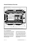
General Hardware Overview
Terminal block for fixed discrete and hardwired inputs
Terminal block for fixed discrete outputs
Captive screw for the input terminal block
Captive screw for the output terminal block
Battery cover
Five terminal screws for
external power connection
PLC status display with
LED indicators
J1 screw for signal
ground-to-chassis ground
J2 screw for 120 Wtermination
of the PLC
Front View of a 512 PLC*
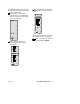
Captive screw for the input terminal block
Captive screw for the output terminal block
* The 612 PLC has an additional set of terminal blocks for analog I/O (see page 11).
The I/O Terminal Blocks
The terminal block at the top of the PLC
provides screw terminal connections for
the 16 fixed discrete inputs and the
high-speed interrupt and counter/timer/
interrupt inputs. The terminal block at
the bottom of the PLC provides screw
terminal connections for the fixed dis-
crete outputs (groups of relay, triac,
and/or FET outputs).
To make field wiring easier, terminal
blocks can be removed from the PLC
base. To remove a terminal block, loos-
en the two captive screws on the left
and right of the block with a slotted
screwdriver until they spring free of their
mating pieces in the unit base. Then
use the screwdriver to pop the block out
of the PLC base.