
Owner's manual

82
ENGLISH
Connection
WARNING
During installation damages may occur!
Have the unit installed by a specialized workshop, if
►
possible.
Please observe all installation and connecting instruc-
►
tions for safe and trouble-free operation if installing
the unit yourself.
CAUTION
Wrong connections may damage the unit.
Use the ISO connectors when installing the unit.
►
Vehicle-specic ISO adapters are available at the
specialized car accessories trade, if necessary.
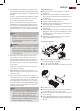
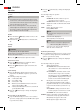
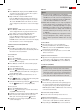
Rear Panel Connections
A
C BDE
A ISO connector B (speakers)
B Vehicle at fuse (5 A)
C ISO connector A (power supply)
D LINE OUT:
RCA audio output L/R for amplier
E Antenna connector
Conguration ISO Connectors
ISO connector A 1 Not connected
2 Not connected
3 Not connected
4 Continuous plus (memory)
5 Control voltage for electron-
ic/motor antenna or power
amplier
6 Not connected
7 12 V (ACC)
8 GND
ISO connector B
1 Speaker rear right +
2 Speaker rear right -
3 Speaker front right +
4 Speaker front right -
5 Speaker front left +
6 Speaker front left -
7 Speaker rear left +
8 Speaker rear left -
CAUTION
Use speakers with an impedance of at least 4 Ohm.
►
The speaker cabling must be oating ground.
►
NOTE
For connecting the unit to two speakers only use only
►
front speaker cables.
Please observe that for the station memory connec-
►
tor 4 must be connected to continuous positive.
In some vehicle models the standard conguration
►
for connectors [4] and [7] (ISO A) is inverted. In this
case the station preset can get lost. To remedy invert
these connections 7 (ACC) and 4 (continuous posi-
tive).
Auto Antenna Power Supply A5 (ISO A)
CAUTION
Damage to the unit is possible!
Do not connect the terminal for antenna power to
►
the power supply of the antenna.
Max. load: 100 mA.
►
The terminal for antenna power is provided for a relay-
controlled antenna. The relay automatically extends the
antenna when the radio is turned on. The antenna retracts
again when the radio is turned o. This terminal can also
be used for an external amplier. Please nd details in the
amplier’s manual.
Connect External Amplier
Connect an external amplier via LINE OUT. Please nd
details in the amplier’s manual.
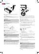
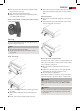
Installation and Removal
The unit can be installed in any ISO installation slot. Please
contact the car manufacturer or the local dealer if your
vehicle does not come with an ISO slot.
NOTE
Before installation remove the two transport securing
►
screws.
Connect all cables before mounting the unit. Ensure
►
all connections are correct and the system works
properly.
Important additional information for installation of
your car radio!
1. The set is designed for an installation where the nega-
tive pole of the battery must be connected to the
vehicle chassis. Please check this before installation.
2. Please note for installation/connection of your set
that not every vehicle is equipped with an “ISO
connection”. In this case we recommend the use of a
vehicle-specic ISO adapter.
Adapters are available from car accessory sellers and/
or your car workshop.