
Operating instructions


Table Of Contents
- 1 Notes on these Operating Instructions
- 2 General Information
- 3 Safety
- 4 Set-Up and Operation
- 5 Commissioning
- 6 Electrical Start-Up
- 7 Interfaces and communication
- 8 Signalling and Error Correction
- 9 Parallel operation
- 10 Maintenance
- 11 Storage, Dismantling and Disposal
- 12 Glossary
38
the inverter and the battery charger takes over charging the
battery.
The LED bargraph (LED chain on the left hand side of the ON
/ OFF button) show during operation the actual utilization of
the UPS (chapter 8.1.1, page 45).
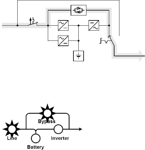
6.1.3 Bypass Operation
Shematic
illustration
Battery
Manual
bypass
Manual bypass path
Mains input
circuit breaker
Mains
Load
Energy flow with
faulty rectifier
Charger
REC
INV
SBS
Safety
bus-bar
If the inverter is overloaded or if overtemperature is detected,
e.g. also if an inverter defect is detected, voltage is supplied
to the load via the bypass that switches on automatically. This
is signalled by the bypass symbol.
This function is also referred to as passive redundancy. It
Protects against total failure of the voltage supply on the
Protected busbar, however in the operating status that is now
attained, mains faults would have a direct effect on the load.
As a result, the electronics continuously attempt to switch
back to "online" / normal operating status (e.g. when the
overload or overtemperature no longer applies).
The bypass is a mechanical link that switches extremely
rapidly. It is located between the load and the mains. The
associated synchronisation unit in the bypass ensures that