
Operating instructions


Table Of Contents
- 1 Notes on these Operating Instructions
- 2 General Information
- 3 Safety
- 4 Set-Up and Operation
- 5 Commissioning
- 6 Electrical Start-Up
- 7 Interfaces and communication
- 8 Signalling and Error Correction
- 9 Parallel operation
- 10 Maintenance
- 11 Storage, Dismantling and Disposal
- 12 Glossary
39
EN
the frequency and phase of the inverter voltage is
synchronised with the mains.
The LED b
ar graph functions as display for USP
utilisation. The signal goes off during this
operations status every 2 seconds.
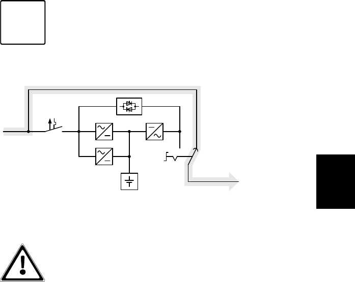
6.1.4 Manual bypass
Battery
Manual
bypass
Manual bypass path
Mains input
circuit breaker
Mains
Shematic
illustration
Load
Energy flow with
active manual
bypass
Charger
REC
INV
SBS
Safety
bus-bar
The manual bypass allows maintenance and service
personnel to work on the Protect C without switching of the
appliance.
If the mains supply fails if the manual bypass is
activated, the loads supply fails completely. For
this reason, it is important to switch as fast as
possible to normal operation mode.
6.1.5 Unit Overload
The load on the UPS should never exceed the specified rated
load of the unit. If a unit overload occurs nevertheless (from
105% of the specified unit rated load) the fault LED is turned
on accompanied with a signal tone (twice per second). The
connected loads continue to be supplied for a certain time
depending on the level of the overload. However, the
connected load must be reduced without delay.
Non-observance of the "Unit overload" condition may cause
the total loss of all UPS functions!
Also avoid short-term unit overloads, which may, for example,
occur when connecting a laser printer or laser fax machine.
i