
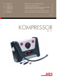
Instruction Manual


14 GB 15 GB
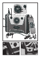
Exchange fuse on the 12 V
vehicle-connection
Release (and remove) the knurled ring
11
, by
turning it against the clockwise direction.
Remove the defective fuse and replace it
with a new one, max. 10 amps.
Screws the knurled ring
11
again firmly, by
turning it in the clockwise direction
Error tracing
The manometer display
2
does not shine.
Check, if the12 V vehicle- connection
10
is
inserted completely and correct and voltage
is on. (POWER-LED on 12 V vehicle-connec-
tion
10
shines).
Check, if the POWER-LED on 12 V vehicle-
connection
10
shines. If not, check the fuse
of the 12 V vehicle-connection
10
as well as
the fuse on the 12 V-socket of the vehicle.
Despite switched on ON- / OFF-switch
3
(in position
) the device does not start
the pumping procedure.
Turn the ignition key / ignition into the first
position (do not start the engine)
The device does not finish the pre-set
pump procedure automatically.
Ensure that you have followed the operating
instructions correctly.
Ensure that you have pre-set the correct
value.
The power cable and / or the 12 V vehicle-
connection gets hot.
Danger of short circuit - Disconnect the
device immediately from the circuit.
The manometer-display
2
shows the
wrong value or is not readable.
Ensure that the device has measured the ac-
tual tyre pressure, (see chapter „Tyre pressure
check“).
Pull off the 12 V vehicle- connection
10
for
at least 5 seconds from the 12 V-socket of the
vehicle and remove the valve connection
15
from the vehicle. Wait until the manometer-
display
2
shows 0,0 again. Re-start the
procedure again.
The pump procedure is running, but the
tyre does not inflate.
Ensure that the valve-connection
15
is fixed
correctly on the valve of the vehicle.
Ensure that the tyre does not have a puncture.
Maintenance and care
The device is maintenance-free.
WARNING!
Always separate electrical de-
vices from the power supply, before you carry
out service etc.
Switch off the device .
Pull of the 12 V vehicle connection
10
from
the 12 V-socket of your vehicle.
Clean the device with a dry cloth. Do not use
solvents or other aggressive detergents
under any circumstances.
Service
WARNING!
Leave the repair of the
device to qualified technical personnel to
repair. Thus the safety of the device is guaran-
teed and maintained.
WARNING!
Leave the exchange of the
plug or the connecting cable always to quali-
fied technical personnel. Thus the security of
the equipment is guaranteed and maintained.
Operation / Error tracing / Maintenance and care / Service / Warranty
Carry out the desired work procedures as
described in following chapters.
Switch on the compressor by pressing the
ON-/ OFF switch
3
into the position .
Switch off the compressor by pressing the
ON-/ OFF switch
3
into the position .
Pull the 12 V vehicle connection
10
from the
12 V-socket of the vehicle.
Light switch ON / OFF
The light source on the compressor is intended
to better illuminate the working area (valve)
Press the ON-/OFF –switch Light
16
into
position
, to switch on the 3 LED
14
.
Press the ON-/OFF –switch Light
16
into
position
, to switch off the 3 LED
14
.
Set the unit of pressure
(psi, bar or kPa)
Press the button Pressure unit „R“
1
until
the desired pressure unit is shown on the
manometer display
2
.
Tire pressure check
Unwind the high-pressure hose
13
com-
pletely.
Note: Make sure that the power LED at the
12 V vehicle connection
10
lights up. The
manometer display
2
must indicate 0,0
before beginning of the measurement.
Fix the valve connection
15
on the valve of
the vehicle.
If the valve connection
15
is correctly connect-
ed with the vehicle valve, the manometer
display
2
shows the current tire pressure.
If this value corresponds to the recommend-
ed tire pressure for the vehicle, you can
remove the valve connection
15
again.
Tire pressure increase
If the indicated value lies under the recom-
mended tire pressure for the vehicle, proceed for
adjustment as follows:
Press the button pre-setting „+ “
5
respec-
tively the button pre-setting „- “
4
until the
pre-set value of the manometer display
2
corresponds to the correct tire pressure.
Switch on the compressor by pressing the
ON- /OFF- switch
3
into position . The de-
vice increases the tire pressure according to
the pre-set value and switches off automati-
cally.
Remove the valve connection
15
carefully.
Important:
During the pumping procedure do not press
the buttons
4
or
5
.
If you connect the device to the 12 V-supply
of a vehicle but do not start the pumping
procedure, the manometer display
2
switches off after some minutes. You acti-
vate it again, by pressing the button unit of
pressure „R “
1
.
Use delivered valves
In the stowage box cover
6
of the compressor
there are 3 typical valve adapters.
Always consider the manual of the object which
is to be pumped up.
· Racing cycle valve (Presta valve)
7
· Valve for sport balls
8
· Valve for inflatable toy
9
Screw the desired valve on the valve con-
nection
15
. Consider the corresponding
maximum pressure of the object which is to
be pumped up and read the respective
operating manual.
Operation