
Operating instructions

26
For contractors
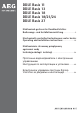
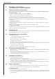
3.1 General installation information
At the factory, the device is prepared for a power connection from the top from an installation below
the plaster (see Fig.
C
-
I
):
s 4HEDEVICEISSUITABLEFORABOVEORUNDERSINKINSTALLATION
C
.
s 7ATERCONNECTIONTHREADEDlTTINGSBELOWTHEPLASTER
s 0OWERCONNECTIONBELOWTHEPLASTERINTHEUPPERDEVICEAREA
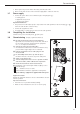
Important information regarding the DDLE Basis 18/21/24 with connected load changeover
In its delivered condition the device is set to 21 kW. When changing to a different output, carry out the
following steps:
s Re-plug the coding card
Re-plug the coding card (
A
8) according to the selected output; for selectable output and fuse protection
see “Specification“.
Mark the connected load on the type plate (
A
19), with a permanent marker.
s Replace the flow limiter
If 24 kW connected load has been selected, replace the fitted flow limiter (
O
30, white) with the flow limiter
supplied ( orange, fixed to the cold water pipe).
3.2 Installation site
Install the instantaneous water heater according to the figure
C
(a-oversink or b-undersink) vertically, flush
with the wall and in a room free from the risk of frost.
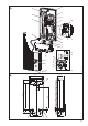
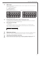
3.3 Preparing the device installation
s /PENTHEDEVICE
D
:
a Disengage the locking device with a screwdriver.
b Open and remove the device cap.
s 2EMOVETHELOWERPARTOFTHEBACKPANEL
E
:
a Push in both locking hooks.
b Remove the lower part of the back panel towards the front.
s "REAKOUTTHECABLEGROMMETKNOCKOUTINTHEBACKPANEL (
F
a). If, by mistake, the wrong knock-out has
been opened, use a new back panel.
s 4RIMTHEPOWERCABLETOSIZE (
F
b).
s 2EMOVETHEPROTECTIVETRANSPORTPLUGSFROMTHEWATERCONNECTIONS.
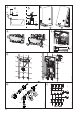
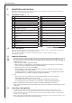
3.4 Fitting the mounting bracket
G
s -ARKOUTTHEHOLESTOBEDRILLEDUSINGTHEINSTALLATIONTEMPLATESUPPLIEDEXISTINGSUITABLE!%'MOUNTING
bracket can be used).
s 3ECURETHEMOUNTINGBRACKETWITHSCREWSANDRAWLPLUGSNOTPARTOFTHESTANDARDDELIVERYSELECTIN
accordance with the material of the fixing wall).
s )NSERTTHESTUDSSUPPLIEDINTOTHEMOUNTINGBRACKET
3.5 Equipment installation
G
s Seal in and insert the twin nipples.
s 0USHTHECABLEGROMMETOVERTHEPOWERCABLE
s 3LIDETHEBACKPANELOVERTHESTUDSANDTHECABLEGROMMETPULLTHECABLEGROMMETWITHAPAIROFPLIERS
against the locking hooks and let both hooks audibly click into place.
s 0USHTHEBACKPANELlRMLYANDmUSHAGAINSTTHEWALLANDLOCKWITHTHElXINGTOGGLE!TTHEBOTTOM
the device can be secure with 2 additional screws (
M
25).
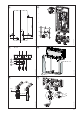
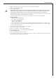
3.6 Water connection
H
s Position the threaded connections with flat packing onto the twin nipples; for this observe the correct
seating of the connections (never twist the bayonet closures inside the device).
Important information:
s 4HOROUGHLYmUSHTHECOLDWATERSUPPLYLINE
s )FTHECORRECTFUNCTIONCANNOTBEASSUREDDUETOINADEQUATEmOWPRESSUREEG-0ABARREPLACE
the flow limiter (
O
30) and reinsert the profile washer (
O
31). If necessary, increase the pressure in the
water installation.
3. Standard installation for contractors
Power: Unfinished walls - top; Water: Unfinished walls