
Operating instructions


Table Of Contents
- OPERATING INSTRUCTIONS
- Table of Contents
- 1 General Information
- 2 Safety
- 3 Scope of Delivery
- 4 Equipment Specifications
- 5 Functional Description
- 6 Storage and Transport
- 7 Installation
- 8 Commissioning
- 9 Operation
- 10 Maintenance
- 11 Decommissioning and Dismantling
- List of Tables
- List of Figures
Protect PV.600/800 OD Series - Operating Instructions
8000041160 BAL Page 15 of 100
i
The protective covers may only be opened/removed for
commissioning and for maintenance work.
After finishing this work, the protective covers must be
closed/mounted again and tested to ensure they are working
correctly.
2.2.3 Voltage Level
For extra-low voltage, protection against electric shock corre-
sponding to protection class III is provided in the case of direct or
indirect touching by means of the SELV system according to
DIN EN 61140 (IEC 60364-4-41).
Conductive housings, covers, mounting plates, dividing walls, etc.
are connected to the PE conductor system.
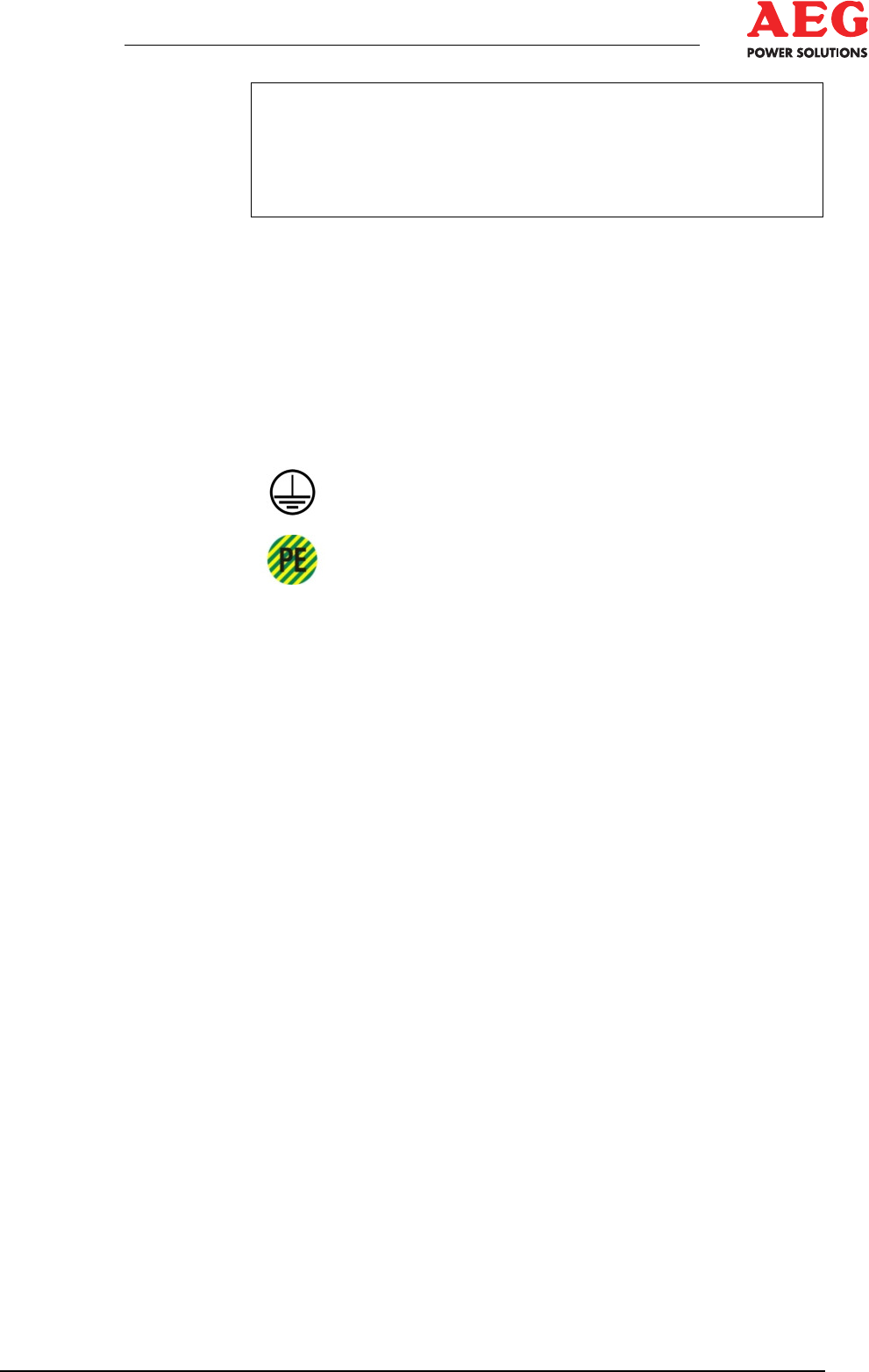
The PE conductor connections are marked with the
5019 symbol in accordance with IEC 417.
In accordance with IEC 60445, the PE conductor can be
identified by the "PE" mark and/or by the
GREEN/YELLOW colour combination.
2.2.4 Lightning Protection
The equipment is effectively earthed and protected against over-
voltage by establishing a connection (DIN VDE 0185) to a suffi-
ciently dimensioned ring earth electrode or an earth connection in
accordance with the specifications set by the grid operator. The
following requirements must be fulfilled as a minimum:
• Recommended cable cross-section: VA4, 3 x 35 mm
2
• Routing:
− Depth: 50 to 100 mm (depending on the local depth of frost
penetration)
− Distance: 1 m from the outer edge of the equipment
− Design: Establish in accordance with the TCC of the grid op-
erator.
The manufacturer’s specifications must be implemented effectively
in order to provide the photovoltaic equipment with suitable light-
ning protection measures.
2.3 Fire Protection
Fire, open flames and smoking are prohibited in and around the
operating area. Inflammable or explosive material must not be
stored in the operating area.
An additional DC isolating point (fire service switch) must be pro-
vided in the immediate vicinity of the PV generators (GCB).
( Chapter 2.2.2 - Disconnecting Protection Device)