
Operating instructions


Table Of Contents
- OPERATING INSTRUCTIONS
- Table of Contents
- 1 General Information
- 2 Safety
- 3 Scope of Delivery
- 4 Equipment Specifications
- 5 Functional Description
- 6 Storage and Transport
- 7 Installation
- 8 Commissioning
- 9 Operation
- 10 Maintenance
- 11 Decommissioning and Dismantling
- List of Tables
- List of Figures
Protect PV.600/800 OD Series - Operating Instructions
Page 26 of 100 8000041160 BAL
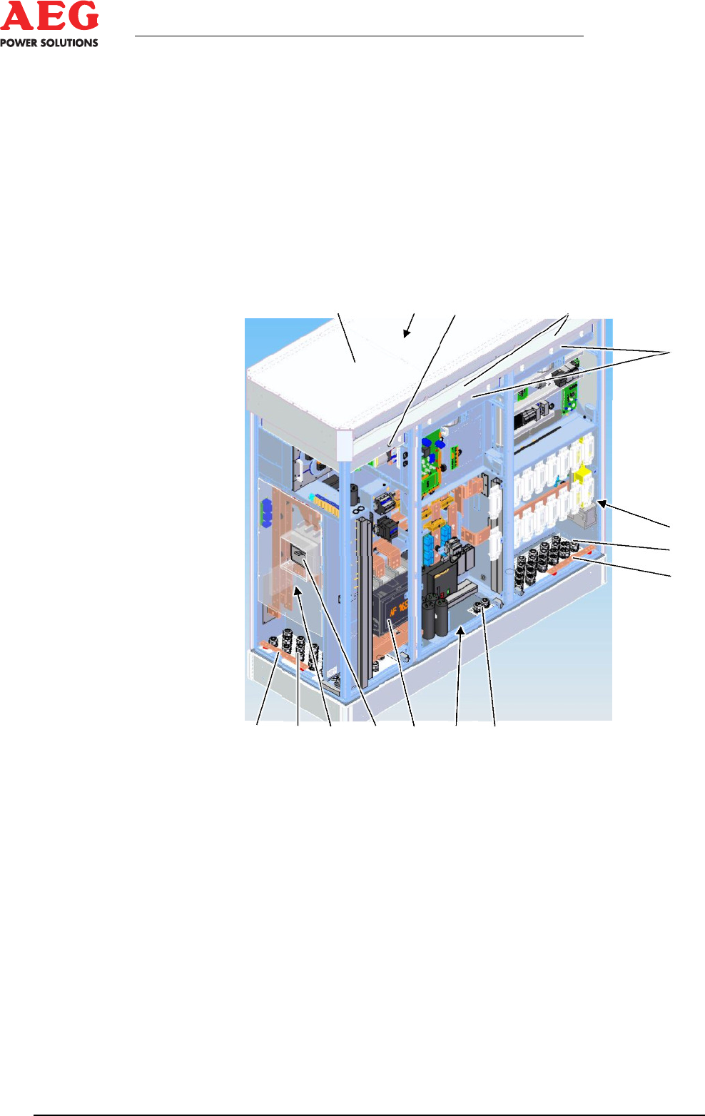
The DC supply with input fuses A41.x and, as an option, a
•
PV inverter input current measurement system from the
PV.IcX generator connection boxes of the PV mod-
ules-Modulen
The PV inverter plus its IGBT stacks and downstream si-
•
nusoidal smoothing-Inverter
The LV main distributor with load interrupter Q26 and the
•
AC outputs
The LV main distribution and all communication connections are
accommodated in the AC cabinet.
1 2 3 4
5
6
7
8
8 13 12 11 10 9 7
Figure 2 - Protect PV.630-OD
1 Equipment roof
2 Radial ventilators
3 Pressure chamber bypass
4 Interior air conditioning
5 Inverter pressure chamber
6 DC/AC section with
NH4 input fuse
7 DC connection PG cable glands
8 Earth bar
9 INV cabinet
10 Switch contactor K7
11 Interrupter switch Q26
12 LV main distributor with
communication connections
13 AC connection
PG cable glands
4.3 Dimensions
The dimensions are specified in the dimensional drawing (*.DD).
The mass information can be found in the technical data or the
transportation documentation.