
Operating instructions


Table Of Contents
- OPERATING INSTRUCTIONS
- Table of Contents
- 1 General Information
- 2 Safety
- 3 Scope of Delivery
- 4 Equipment Specifications
- 5 Functional Description
- 6 Storage and Transport
- 7 Installation
- 8 Commissioning
- 9 Operation
- 10 Maintenance
- 11 Decommissioning and Dismantling
- List of Tables
- List of Figures
Protect PV.600/800 OD Series - Operating Instructions
8000041160 BAL Page 27 of 100
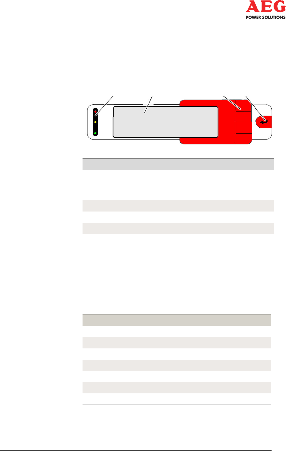
4.4 Operating and Display Elements
4.4.1 Display and Operation Unit
The display and operation unit is integrated into the front of the
Protect PV.6x0/8x0-OD equipment, and is used for signalling and
visualising equipment data as well as for on-site control purposes.
1 2 3 4
Figure 3 - Display and operation unit
Item Component Function
1
LED illuminated indicators
red
yellow
green
Process status display
2
Graphical display (LCD) Menu display
3
4x function keys Menu control
4
ENTER key Confirmation
Table 6 - Display and operation unit
The graphical LCD shows equipment statuses and measured val-
ues using symbols and plain text. The system can be parameter-
ised and controlled using menus which are protected via pass-
word.
4.4.2 LED Equipment Status
The global equipment status can be read from the 3 LEDs.
LED Signal
red on
Deactivating fault present
flashing red
Self-acknowledging deactivating fault present
flashing yellow
Self-acknowledging fault present
green off
INV in sleep mode
flashing green 1 Hz
INV waiting for feed conditions
flashing green 0.5 Hz
INV feeding into mains with derating
green on
INV feeding into mains
Table 7 - Assignment of the LED illuminated indicators