
Operating instructions


Table Of Contents
- OPERATING INSTRUCTIONS
- Table of Contents
- 1 General Information
- 2 Safety
- 3 Scope of Delivery
- 4 Equipment Specifications
- 5 Functional Description
- 6 Storage and Transport
- 7 Installation
- 8 Commissioning
- 9 Operation
- 10 Maintenance
- 11 Decommissioning and Dismantling
- List of Tables
- List of Figures
Protect PV.600/800 OD Series - Operating Instructions
8000041160 BAL Page 29 of 100
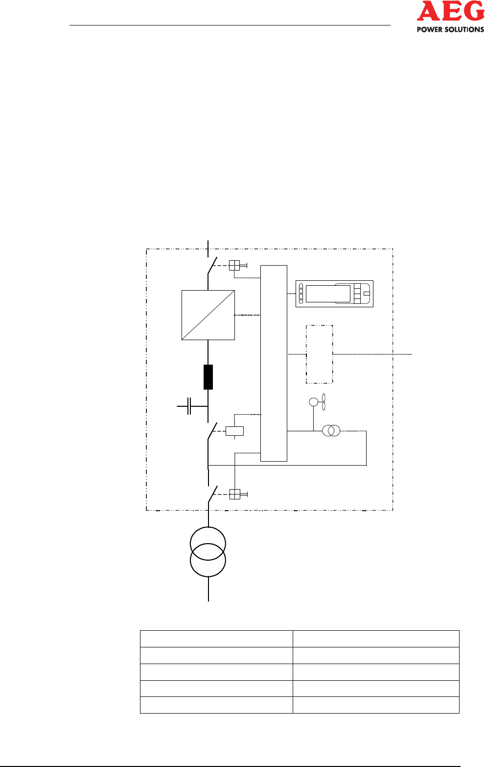
4.5 Supply
The main assemblies of the inverter are:
DC load interrupter switch Q4
•
DC filter
•
Inverter stack, display and control unit with communication
•
components
AC filter L26
•
INV output contactor K7
•
Load interrupter switch Q26
•
Mains transformer (external)
•
Figure 4 - Functional principle - Medium-voltage supply
DC (PV-Module) DC (PV modules)
Display Display
Steuergerät Control unit
Kommunikation Communication
Steuergerätversorgung Control unit supply
=
~
~
~
M
D
C
(PV-Module)
Q4
K7
Q26
Mittelspannungs-Netz
Steuergerät
Steuergerätversorgung
Kommunikation
Display