
Operating instructions


Table Of Contents
- OPERATING INSTRUCTIONS
- Table of Contents
- 1 General Information
- 2 Safety
- 3 Scope of Delivery
- 4 Equipment Specifications
- 5 Functional Description
- 6 Storage and Transport
- 7 Installation
- 8 Commissioning
- 9 Operation
- 10 Maintenance
- 11 Decommissioning and Dismantling
- List of Tables
- List of Figures
Protect PV.600/800 OD Series - Operating Instructions
Page 32 of 100 8000041160 BAL
4.6 Interfaces
PV power stations are generally monitored centrally and therefore
communication interfaces such as relay contacts, optocouplers,
and various serial interfaces with protocols are available for inte-
gration as standard.
The central communication unit of the Protect PV is equipped with
an "MCC MultiCom interface".
Central monitoring can be carried out via the Internet, using the
AEG monitoring component PV.LoG. The PV inverter connection
is established via the Modbus protocol and has been optimally
adapted for monitoring and management purposes.
The CAN bus is used for exchanging information between the indi-
vidual modules and for remote signalling for central monitoring
purposes.
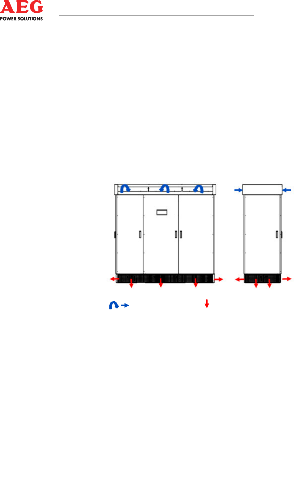
4.7 Ventilation
Figure 6 - PV.630-OD air currents
Supply air Exhaust air
In the Protect PV.6x0/8x0-OD, the interior air conditioning assem-
bly ensures the required air current of approx. 4000 m
3
/h ( tech-
nical data) for cooling the equipment.
The fresh air is drawn into the pressure chambers using radial ven-
tilators and through the ventilation grilles in the roof, and is then
compacted and pressed into the interior. The IGBT inverter stack
is cooled using an air current in the ventilation duct. The use of the
air current can be increased to a specific level by installing heat
sinks on sensitive assemblies (IGBT stack). Additional heat ex-
changers increase the efficiency of the interior air conditioning.
The supply air is output downwards through the base as a a result
of overpressure in the equipment.
The equipment sleeving is designed with double walls and has
ventilation openings for convective cooling.
The ventilation openings on the equipment must not be obstructed
or adjusted.