
Operating instructions


Table Of Contents
- OPERATING INSTRUCTIONS
- Table of Contents
- 1 General Information
- 2 Safety
- 3 Scope of Delivery
- 4 Equipment Specifications
- 5 Functional Description
- 6 Storage and Transport
- 7 Installation
- 8 Commissioning
- 9 Operation
- 10 Maintenance
- 11 Decommissioning and Dismantling
- List of Tables
- List of Figures
Protect PV.600/800 OD Series - Operating Instructions
Page 52 of 100 8000041160 BAL
• Screw the eye bolts fully into the threaded holes. The bottom
flange must lie completely flat and flush with the surface of the
cabinet.
• Fasten the supporting bracket with screw connections in the
threaded holes of the INV and AC cabinet.
• Calculate the length of the ropes (chains, ropes or straps) in
such a way that an angle of >45° (F2) is formed between the
sling gear and the top of the cabinet. The ropes (DIN EN 1492)
must always be of the same length to ensure uniform load dis-
tribution and avoid tilting of the equipment.
• The load-bearing capacity of each item of sling gear must have
a capacity of at least half of the cabinet weight as a precaution.
• Use one rope per transport eyelet, i.e. four per cabinet and a
total of eight per unit.
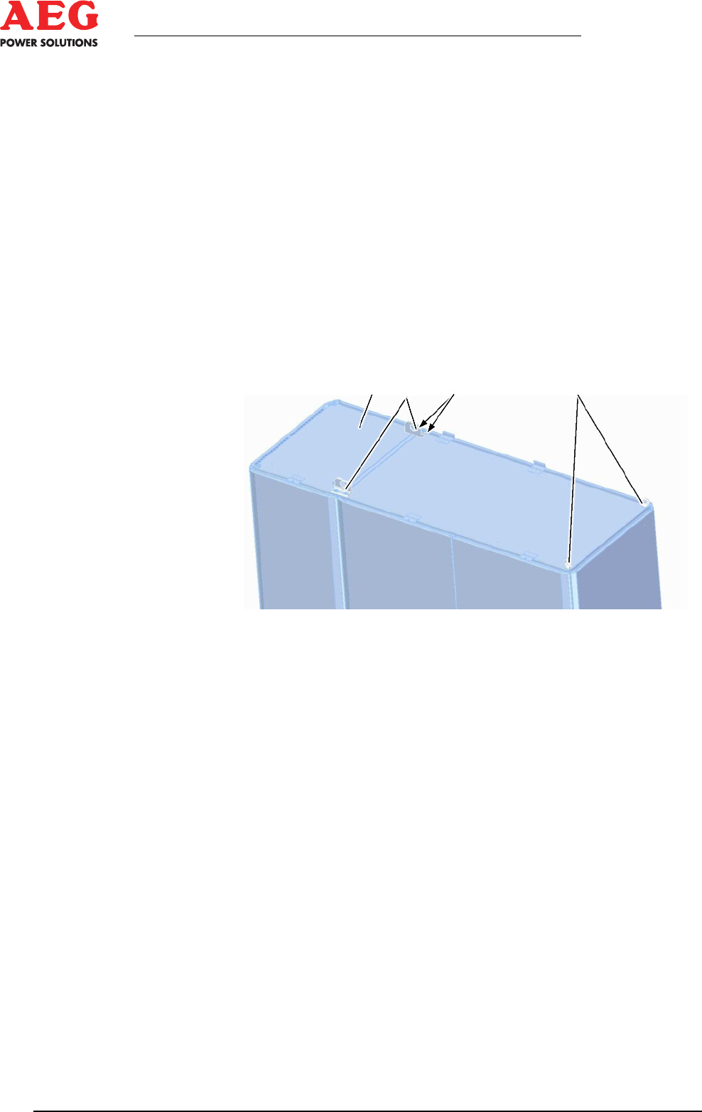
1 2 3 4
Figure 12 - Lifting points
1 Top of the cabinet without roof
2 Supporting bracket
2 Threaded hole
4 Eye bolt
Implementation
1. Check the lifting points and the sling gear for damage and re-
place immediately if you identify any tears or deformation.
2. Attach the ropes to the transport eyelets.
3. Check that the transport eyelets and ropes are fastened cor-
rectly.
4. Unscrew and remove the screw connections from the transport
pallet. If necessary, remove the ventilation grids first.
5. Carefully lift the equipment and transport it to its intended in-
stallation location.
6. Lower the equipment carefully, feed the cables into it from be-
low terminal diagram (*.TD), position it at the installation lo-
cation and set it down without any jolts.
7. Check the stability of the equipment and secure it at the instal-
lation location.
8. Remove the sling gear and the lifting points.
9. Put the roof on and secure it.