
Operating instructions


Table Of Contents
- OPERATING INSTRUCTIONS
- Table of Contents
- 1 General Information
- 2 Safety
- 3 Scope of Delivery
- 4 Equipment Specifications
- 5 Functional Description
- 6 Storage and Transport
- 7 Installation
- 8 Commissioning
- 9 Operation
- 10 Maintenance
- 11 Decommissioning and Dismantling
- List of Tables
- List of Figures
Protect PV.600/800 OD Series - Operating Instructions
Page 56 of 100 8000041160 BAL
Note:
The area for setting up the equipment must be dry and level; if
necessary, even out the area and install the equipment at a slight
elevation.
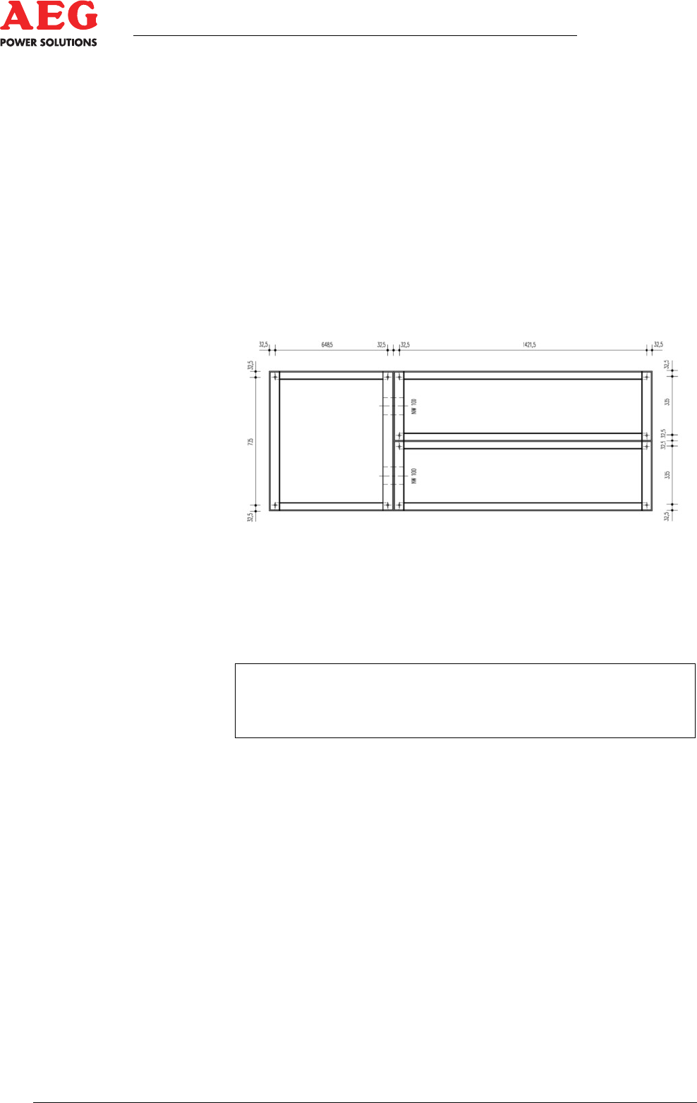
Each frame post of the cabinet has a welding plate with a bore
of Ø 20 for attaching to the floor. This bore is where the fixing bolt
is screwed in ( dimensional drawing).
It is essential that you comply with the installation conditions
( Chapter 2.1.1).
Implementation
1. Align the equipment horizontally and vertically to avoid defor-
mations.
Figure 14 - Lightweight concrete base fixing points
2. Fasten the equipment to the foundation/base and establish an
M12 screw connection using the relevant tightening torque.
3. Attach the ventilation grilles after inserting the connection lines.
i
After installing the station and filling the foundation, the area
approximately 1 m around the installation must be kept free
from vegetation.