
Operating instructions


Table Of Contents
- OPERATING INSTRUCTIONS
- Table of Contents
- 1 General Information
- 2 Safety
- 3 Scope of Delivery
- 4 Equipment Specifications
- 5 Functional Description
- 6 Storage and Transport
- 7 Installation
- 8 Commissioning
- 9 Operation
- 10 Maintenance
- 11 Decommissioning and Dismantling
- List of Tables
- List of Figures
Protect PV.600/800 OD Series - Operating Instructions
Page 58 of 100 8000041160 BAL
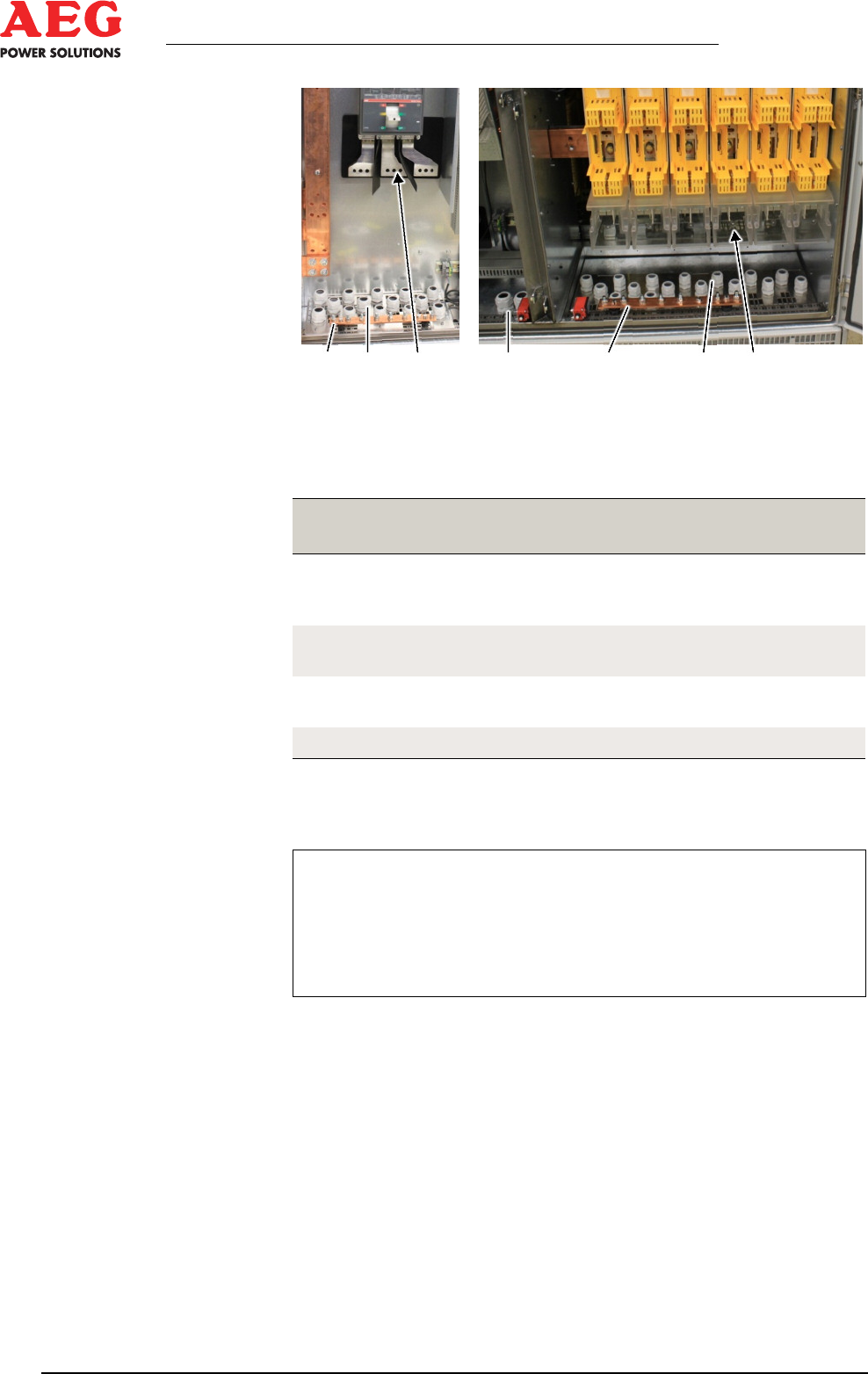
1 2 3 2 1 2 4
Figure 15 - Connection panels
1 Earth bar
2 PG cable glands
3 AC output
4 DC input
Installation
location
Connection Cross-section
-X41:1L+, 1L-
to
-X41:8L+, 8L-
DC input maximum 185 mm²
-X3:U, V, W AC mains maximum
3x240 mm²/phase
PE Earthing minimum 3x95 mm
2
maximum 3x185 mm²
-X13:U, N, PE Auxiliary power supply 3 x 1.5 mm
2
Table 12 - Power terminals
*) minimum depends on the number of inputs used.
i
Establish connections according to the circuit diagram.
The mains connection line for the independent power supply
must be protected by the circuit breaker specified in the tech-
nical data sheet.
For connection cross-sections, see
circuit diagram and
technical data.
Implementation
1. The equipment and power cable must be safely disconnected.
2. Open the cabinet door, remove the protective cover.
3. Open the PG cable glands in the base of the cabinet.
4. Insert the power cables in the required lengths.
5. Press on the cable lug and screw into place on the correspond-
ing busbar ( circuit diagram *.CD) using the relevant tighten-
ing torque.