
Operating instructions


Table Of Contents
- OPERATING INSTRUCTIONS
- Table of Contents
- 1 General Information
- 2 Safety
- 3 Scope of Delivery
- 4 Equipment Specifications
- 5 Functional Description
- 6 Storage and Transport
- 7 Installation
- 8 Commissioning
- 9 Operation
- 10 Maintenance
- 11 Decommissioning and Dismantling
- List of Tables
- List of Figures
Protect PV.600/800 OD Series - Operating Instructions
8000041160 BAL Page 61 of 100
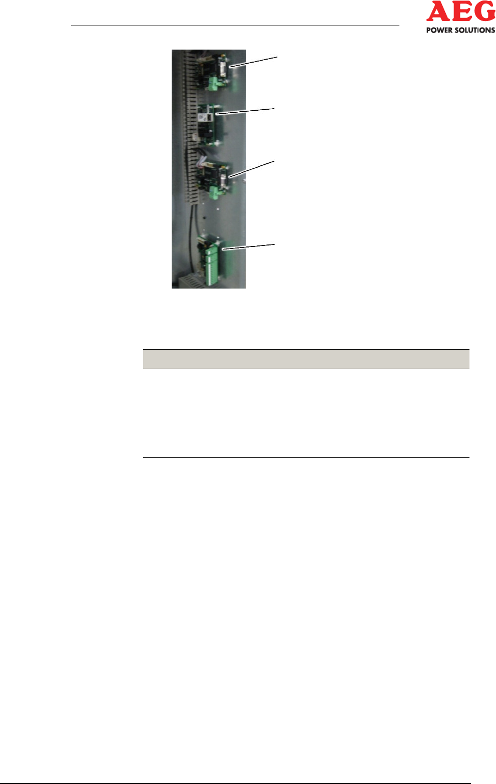
1
2
3
4
Figure 16 - Communication connections (example)
1 A29.1 Modbus
2 A27 Ethernet
3 A29.2 Modbus
4 A12 remote signalling
Item Installation location Connection
1
-A29.1-X5:1-9 CAN bus
2
-A27:1-8 COM server
3
-A29.2 Modbus
4
-A12 Remote signalling
-A13 Remote signalling (optional)
Table 13 - Control/monitoring terminals
7.6.3 Shield Handling on Data Lines
Shielding is a means of weakening (attenuating) magnetic, elec-
trical or electromagnetic interference fields.
Interference currents on line shields are dissipated to earth by
means of the shield busbar that has a conductive connection to the
housing. A low-impedance connection to the PE conductor is es-
pecially important to prevent these interference currents from be-
coming a source of interference themselves. If possible, only use
lines with a braided shield. The coverage of the shield should be
80% or more.
Avoid using lines with a foil shield because tensile and compres-
sive stresses applied when fastening the line can very easily dam-
age the foil, resulting in a reduction in the shielding effect.
Bear the following points in mind when handling the shield:
• Use cable clips or shield terminals made of metal to secure the
braided screen. The clips must surround the shield and have
good contact with it over a large area.