
Operating instructions


Table Of Contents
- OPERATING INSTRUCTIONS
- Table of Contents
- 1 General Information
- 2 Safety
- 3 Scope of Delivery
- 4 Equipment Specifications
- 5 Functional Description
- 6 Storage and Transport
- 7 Installation
- 8 Commissioning
- 9 Operation
- 10 Maintenance
- 11 Decommissioning and Dismantling
- List of Tables
- List of Figures
Protect PV.600/800 OD Series - Operating Instructions
Page 62 of 100 8000041160 BAL
• Route the shield on a shield busbar directly from the point at
which the line enters the cabinet. Route the shield up to the
assembly, but ensure that it does not make contact there.
When used in PV applications, the shield of the RS-485 bus line
should only be earthed on one side so that no equalizing or inter-
ference currents can flow through the shielding. If several bus sta-
tions are present, you must make sure that the shield is never in-
terrupted.
Always attach the shield of the RS-485 bus line to earth on the
quiescent side. This means that only one side of the shield is at-
tached to the earth potential on the Modbus master or data logger
side.
In the Protect PV, the shield must not be connected to the housing
in any way.
Insert the RS-485 bus line into the equipment until it reaches the
MCC Multicom interface, shorten it accordingly, and attach both
wires to terminals "A" and "B" (if you are using a bus cable con-
nector) or pins 3 and 8 of the 9-pin D-Sub connector.
Use a shielded CAN bus line, e.g. 2 x 0.22 twisted pair Lapp
"UNITRONIC-BUS LD".
If you are using the PV.LoG or Skylog data logger and preassem-
bled data lines from AEG PS, plug the bus connector into X5 on
the MCC assembly and route the line to the data logger cabinet.
Shorten the line as appropriate and connect the wires to the corre-
sponding terminals. The shield must be connected to the shield
terminal block at the intended position in the data logger cabinet.
Observe the information in the PV.LoG/Skylog manual.
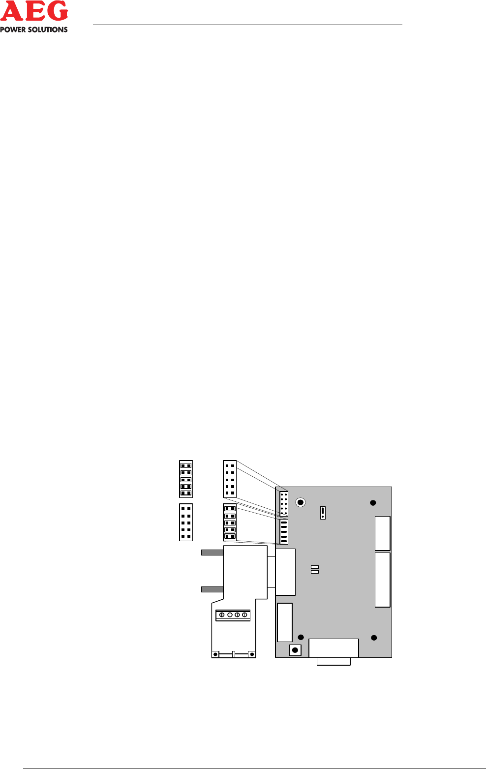
7.7 MCC MultiCom Interface
Modbus Configuration
Figure 17 - MCC MultiCom interface (-A29.1) as Modbus interface (top view)
1
1
1
1
1
1
1
1
X3
X1
X2
X4
X5
J1
J5
J4
LED
gn
rt
S1
RS232:
RS485:
B A B A