
Operating instructions


Table Of Contents
- OPERATING INSTRUCTIONS
- Table of Contents
- 1 General Information
- 2 Safety
- 3 Scope of Delivery
- 4 Equipment Specifications
- 5 Functional Description
- 6 Storage and Transport
- 7 Installation
- 8 Commissioning
- 9 Operation
- 10 Maintenance
- 11 Decommissioning and Dismantling
- List of Tables
- List of Figures
Protect PV.600/800 OD Series - Operating Instructions
Page 64 of 100 8000041160 BAL
Pin number Signal Description
2
RxD PC receiving data from the MCC
3
TxD PC sending data to the MCC
5
GND Interface reference potential
Flange
INV housing potential
Table 16 - Port 1 (X2) RS-232 pin assignment (default)
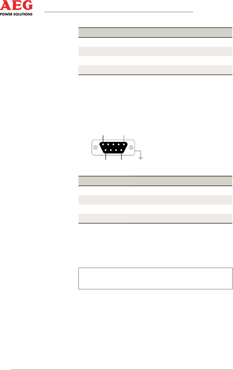
Port 2: Serial interface X5, RS-485 pin assignment
The potential-free RS-485 interface at connector X5 supports the
Modbus protocol for integration into higher-level monitoring sys-
tems.
1
5
6
9
Figure 19 - Serial D-sub connector X5
Pin number Signal Description
3
B High data
8
A Low data
5
GND Interface reference potential
Flange
INV housing potential
Table 17 - Port 2 (X5) RS-485 pin assignment (default)
Use a shielded fieldbus line (e.g. 2 x 0.22 twisted pair Lapp
"UNITRONIC-BUS LD").
Preassembled data lines can be purchased from AEG PS.
i
An RS-485 data bus line must always be terminated with
120 at both ends of the line.
In the case of preassembled data lines, the terminating resistors
are pre-installed. Depending on the setup and wiring, make sure
that only the first and last Modbus stations have a termination of
120 . If necessary, remove any surplus terminating resistors.