
Operating instructions


Table Of Contents
- OPERATING INSTRUCTIONS
- Table of Contents
- 1 General Information
- 2 Safety
- 3 Scope of Delivery
- 4 Equipment Specifications
- 5 Functional Description
- 6 Storage and Transport
- 7 Installation
- 8 Commissioning
- 9 Operation
- 10 Maintenance
- 11 Decommissioning and Dismantling
- List of Tables
- List of Figures
Protect PV.600/800 OD Series - Operating Instructions
Page 68 of 100 8000041160 BAL
T
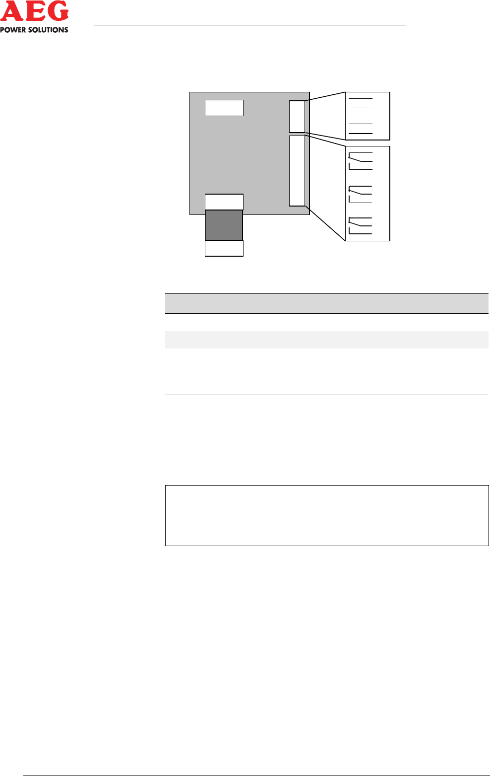
he expansion board has three potential-free contacts and two
control inputs.
1
X2
1
1
X3
X4
X2
X2
1
X1
9
8
7
6
5
4
3
2
1
4
3
2
1
K26(29)
K27(30)
K28(31)
OPT2(4)
OPT3(5)
Figure 22 - Remote signalling expansion board (-A13) (top view)
Item Connections
X1
Remote signalling master board
X2
nn
X3
Remote signalling outputs with relay changeover switches
X4
Remote signalling input via optocoupler with independent
power supply
Table 21 - Terminal assignment for expansion board (-A13)
The signalling contacts X3 and X4 of the master board and the
connector X3 of the expansion board have a maximum load of
500 V, 8 A AC/50 V, 2 A DC.
i
If the specified peak power has been applied to the relay con-
tacts once, the gold alloy may be evaporated, meaning that
those contacts can no longer reliably switch an extra-low volt-
age.
The control input X5 of the master board and the input X4 of the
expansion board are supplied via a dedicated 24 V DC power sup-
ply.
The control signal is activated by bridging the relevant input. There
is no need for an additional auxiliary power supply.
The signals of the master board are assigned as standard.
Maintenance work on the Protect PV can be signalled to the con-
nected monitoring systems via Modbus using the integrated ser-
vice switch S1.
The expansion board is programmed without signals and can re-
ceive customer-specific signals and functions.