
Operating instructions


Table Of Contents
- OPERATING INSTRUCTIONS
- Table of Contents
- 1 General Information
- 2 Safety
- 3 Scope of Delivery
- 4 Equipment Specifications
- 5 Functional Description
- 6 Storage and Transport
- 7 Installation
- 8 Commissioning
- 9 Operation
- 10 Maintenance
- 11 Decommissioning and Dismantling
- List of Tables
- List of Figures
Protect PV.600/800 OD Series - Operating Instructions
Page 70 of 100 8000041160 BAL
Plug Design Description
X1
10-point pin, trough CAN connection
X2
10-point pin Programming connection for host
X3
2-point CombiCon 24 V DC supply
X4-X11
4-point CombiCon Current transformer connections
X12
2-point pin Jumper for CAN addressing
Table 23 - Terminal assignment
The LED signalling can be used to check that the interface is inte-
grated correctly.
H100
green
H101 red Signal
Flashing Flashing
Assembly is booting/commissioning/
SW test
ON OFF CAN connection to PV inverter OK
OFF ON CAN addressing incorrect
ON Flashing Communication fault with the PV inverter
OFF Flashing CAN fault
Table 24 - Communication LED signals (CPU)
LED Status Signal
H102 ON ±15 V supply collective signal OK
H400 ON +24 V supply OK
H401 ON +15 V supply individual signal OK
H402 ON +3.3 V supply for cluster OK
H404 ON -15 V supply individual signal OK
Table 25 - Supply LED signals
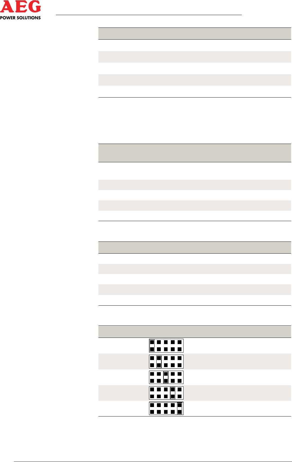
CAN address PIN
1
2
3
4
5
Table 26 - CAN addressing X1