
Operating instructions


Table Of Contents
- OPERATING INSTRUCTIONS
- Table of Contents
- 1 General Information
- 2 Safety
- 3 Scope of Delivery
- 4 Equipment Specifications
- 5 Functional Description
- 6 Storage and Transport
- 7 Installation
- 8 Commissioning
- 9 Operation
- 10 Maintenance
- 11 Decommissioning and Dismantling
- List of Tables
- List of Figures
Protect PV.600/800 OD Series - Operating Instructions
Page 72 of 100 8000041160 BAL
Read and understand the operating instructions before com-
missioning.
8.2 Connection of AC Voltage
Prerequisites
• 3-pin phase-rotation indicator
• 4 measuring instruments/multimeters
• 2-pin voltage detector
• Circuit diagram
• All miniature circuit breakers are switched on
• All circuit breakers and load interrupters are switched off
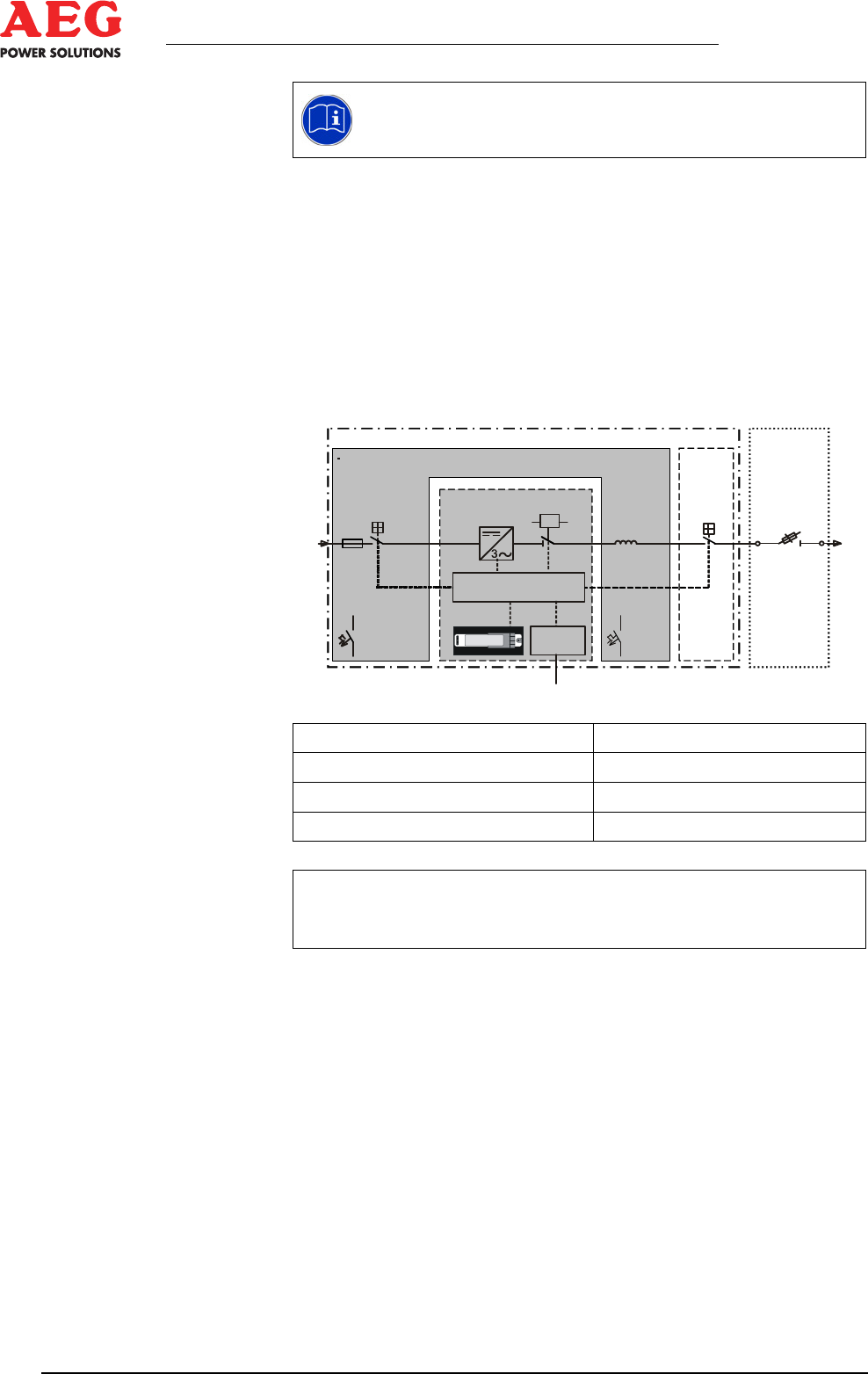
Figure 24 - Functional principle with miniature circuit breakers
DC (PV-Modul) DC (PV module)
Control Control
Com Com
EVU-Netz Mains Power utility mains
i
Isolating points Q1 are designed on a system-specific basis
and do not form part of the Protect PV.600/800.
-F41
-Q4.1
-Q1
12
Protect PV.500
-F13,
-F22,
-F60,
-F61,
-F101
-F38,
-F81
-A1
-K7
-L26
-Q26
Com
Control
D
C
(
P
V
-
M
o
d
u
l
)
EVU-Netz
Mains
+DCD/ACD
+INV
+NSHV