
Operating instructions


Table Of Contents
- OPERATING INSTRUCTIONS
- Table of Contents
- 1 General Information
- 2 Safety
- 3 Scope of Delivery
- 4 Equipment Specifications
- 5 Functional Description
- 6 Storage and Transport
- 7 Installation
- 8 Commissioning
- 9 Operation
- 10 Maintenance
- 11 Decommissioning and Dismantling
- List of Tables
- List of Figures
Protect PV.600/800 OD Series - Operating Instructions
8000041160 BAL Page 73 of 100
Preparatory work
Before connecting the AC voltage, check the following:
• Auxiliary power supply circuit selection circuit 1 or circuit 2
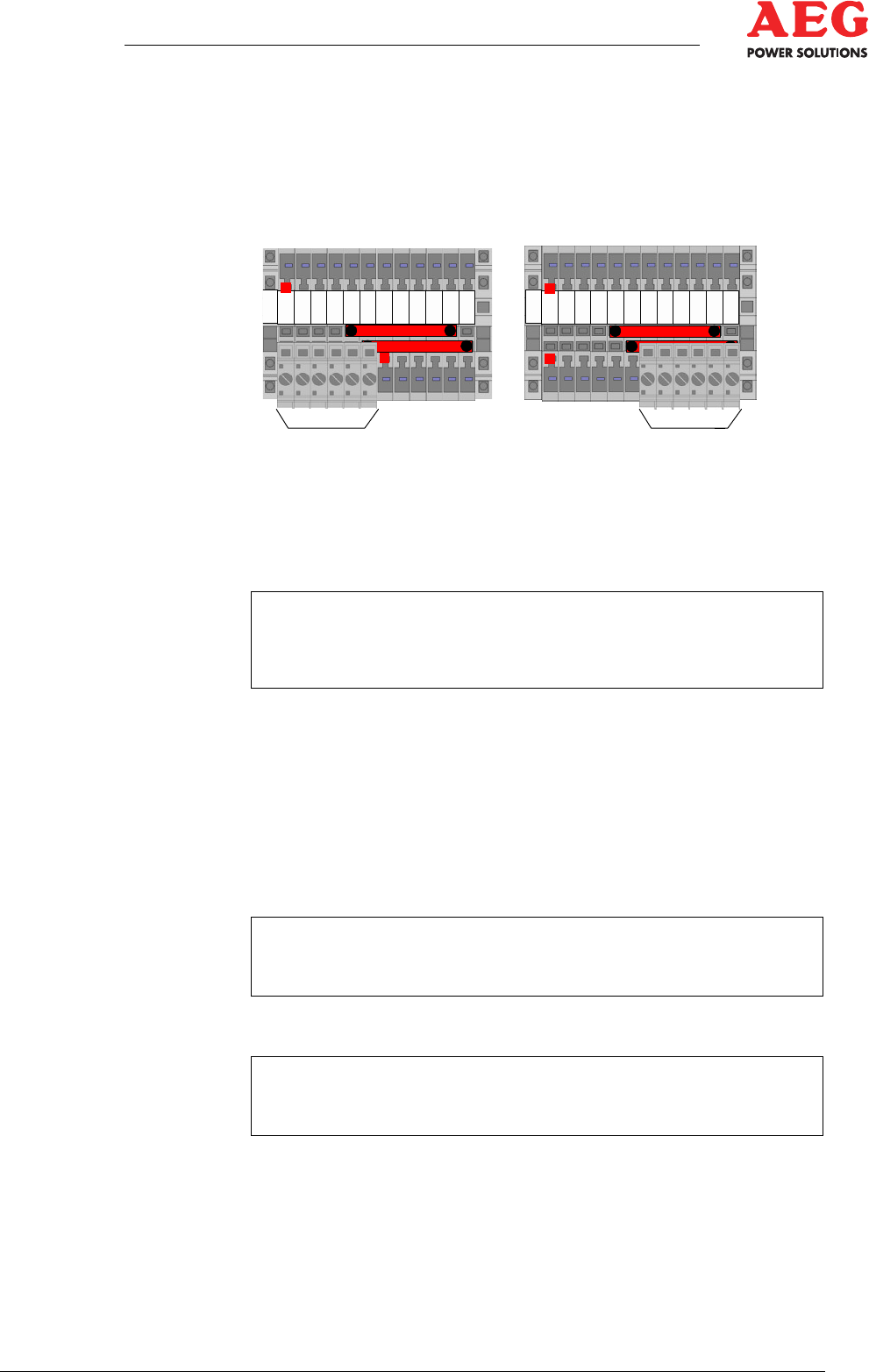
• Select the auxiliary power supply circuit by positioning the
bridge block on terminal X14.
Figure 25 - Terminal assignments X14
1
Bridge block 1 Auxiliary power supply via external circuit 2
F60 (E1:L/N/PE; 230 V AC)
2
Bridge block 2 Auxiliary power supply via internally generated
circuit 1; F61 (factory settings)
i
The bridge block must not be replaced in the "Operation" sta-
tus. The Protect PV cannot be switched without a bridge
block.
• F60, F61 switched off (DC/AC control cabinet).
• F14 switched off (DC/AC control cabinet).
• Q4.1 switched off (DC/AC control cabinet).
• Q26.x switched off (external).
• F41 not engaged (DC/AC control cabinet).
• F22, F13, F101 switched on (DC/AC control cabinet).
i
The low-voltage winding of the mains transformer must not be
connected to earth.
Implementation
i
An insulation test must be performed before the mains voltage
is connected.
1. Perform an insulation test.
2. Connect the MV switchgear.
Voltage is present at the external mains isolating point.
1
122 334 4556 6778 899
1
0
1
0
1
1
1
1
1
2
1
2
X14
X14
12