ELFAMATIC V 3000 Deutsch Aufladesteuerung Gebrauchs- und Montageanweisung ELFAMATIC V 3000 English Charge control Operating and Installation instructions ELFAMATIC V 3000 Français Régulation de charge Notice d'utilisation et de montage ELFAMATIC V 3000 Oplaadregeling Gebruiks- en Montagehandleiding -10 -5 -15 10 15 0 -20 +5 -25 +11 5 20 0 25 E1 E2 40 ELFAMATIC V 3000 ED 60 20 80 0 100 Ab Nederlands
Deutsch English Inhaltsverzeichnis Table of Contents 1. Gebrauchsanweisung Für den Benutzer 1.1 Gerätebeschreibung __________________ 3 1.2 Bedienung __________________________ 3 2. Montageanweisung Für den Installateur 2.1 Vorschriften und Bestimmungen ________ 6 2.2 Technische Daten ____________________ 6 2.3 Montage ___________________________ 6 2.3.1 Steuerung _____________________ 6 2.3.2 Elektrischer Anschluss ____________ 7 2.4 Inbetriebnahme _____________________ 8 3.
Für den Benutzer Deutsch 1. Gebrauchsanweisung 1.1 Gerätebeschreibung Die Aufladesteuerung ELFAMATIC V 3000 berechnet ständig den richtigen Wärmevorrat der Wärmespeicher.
Für den Benutzer Einsteller „E2“ (Ladebeginn) Mit dem Einsteller E2 wird die Außentemperatur in °C eingestellt, bei der die Aufladung beginnen soll. Dabei können individuelle Benutzergewohnheiten berücksichtigt werden. Bei Außentemperaturen oberhalb des Einstellwertes E2 erfolgt keine Aufladung. Sollte bei milden Außentemperaturen zu viel oder zu wenig Wärme zur Verfügung stehen, kann an dem Einsteller E2 eine Korrektur der Auflademenge vorgenommen werden.
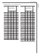
Für den Benutzer E2 -12 °C -14 °C -16 °C 4+0 -12 -14 -16 18 4+4 4 3 2 4+7 8 8 5+0 -12 5+1 Freigabezeit LF + LZ E1 (Vollladung) bei einer Soll-Raumtemperatur ϑR = 20 °C und Außentemperatur ϑa von . . . E2 -12 °C -14 °C -16 °C Ladebeginn E1 (Vollladung) bei einer Soll-Raumtemperatur ϑR = 20 °C und Außentemperatur ϑa von . . .
Für den Installateur 2. Montageanweisung 2.1 Vorschriften und Bestimmungen ● ● ● ● Montage und elektrischer Anschluss müssen von einem Fachmann unter Beachtung dieser Montageanweisung durchgeführt werden. Alle elektrischen Anschluss- und Installationsarbeiten sind nach den VDE-Bestimmungen (0100), den Vorschriften des zuständigen EVU’s sowie den entsprechenden nationalen und regionalen Vorschriften auszuführen.
Austausch gegen eine vorhandene ELFAMATIC V 2100 Das Gerät muss entsprechend dem Schaltplan angeschlossen werden. Deutsch Für den Installateur Ersatzsicherung Demontage Zum Ausbau der Steuerung das Oberteil vom Sockel lösen (wie vorher beschrieben) und Anschlussleitungen abklemmen. Danach den Sockel wie in nebenstehender Abbildung gezeigt von der Schiene lösen. 2.3.2 Elektrischer Anschluss OFF OFF OFF Dip 2 OFF OFF 2. Z1/Z2 bis max. 300 W belastbar.
Für den Installateur 2. An W1 und W2 der ELFAMATIC V 3000: Witterungsfühler R = siehe nebenstehendes Diagramm ● Netzspannung einschalten und zwischen L und N messen ● LF-Freigabe simulieren und Spannung zwischen LF und N messen ● Netzspannung ausschalten Das Gehäuseoberteil auf den Sockel aufstecken. Die Vorprüfung ist beendet.
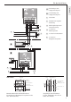
2 A Einzelanlage ohne Gruppensteuergerät B Zentralanlage mit Gruppensteuergerät 1 Ladeschütz 2 Schaltuhr für mögliche Absenkung 3 EVU-Freigabesignal und Laufzeitsteuerung 4 zu weiteren Wärmespeichern 5 zu weiteren Ladeschützen 6 zu weiteren Gruppensteuergeräten 3 1 5 Deutsch Für den Installateur 4 4 6 Fühlereinbau Mauerwerk Beton Witterungsfühler ∅11,5 mm (Bohrung ∅12 mm) ca. 10˚ ca. 10˚ Wärmedämmstoff Wärmedämmstoff Witterungsfühler ∅11,5 mm (Bohrung ∅12 mm) Beton, Eternit o.
Kundendienst und Garantie 3. Kundendienst und Garantie Informationen zu Kundendienst- und Garantiebedingungen finden Sie in unserem Beiblatt »Kundendienst und Garantie«. 3.1 Entsorgung von Verpackung und Altgerät Verpackungsmaterial entsorgen Entsorgen Sie das Verpackungsmaterial des Gerätes sachgerecht. Transportverpackungen überlassen Sie dem Fachhandel. Verkaufsverpackungen (Grüner Punkt) entsorgen Sie über DSD (Duales System Deutschland).
For the User 1. Operating instructions 1.1 Description of device 53 mm -10 -5 10 54,8 mm 44 mm 15 0 -20 +5 -25 +11 5 20 0 25 E1 E2 40 ELFAMATIC V 3000 ED 45 mm 90 mm -15 6 mm English The charging controller ELFAMATIC V 3000 continuously calculates the correct amount of thermal energy stored in the storage heaters.
For the User Adjuster “E2” (charging start) Adjuster E2 is used to set the outside temperature (°C) at which charging is to begin. Specific habits of users can be taken into consideration. No charging is performed at outside temperatures above the setting value E2. If too much or not enough heat is available in the case of mild outside temperatures, the charging rate can be corrected at the adjuster E2. To prevent incorrect settings, it is advisable to alter the adjuster only gradually, e.g.
For the User Setting examples for E1 and E2 with forward control -14 °C -16 °C 4+0 -12 -14 -16 18 4+4 4 3 2 4+7 8 8 5+0 -12 5+1 E2 -12 °C -14 °C -16 °C 8+0 -12 -14 -16 18 18 8+2 -6 -7 -9 18 7 18 8+2+2 -1 -3 -4 18 -14 -16 18 8+2+4+2 4 3 2 18 -7 -8 -10 18 8 + 2,5 -4 -6 -7 18 5+3 0 -1 -3 18 8+3 -3 -5 -6 18 5 + 11 10 9 8 18 8 + 3,5 -2 -4 -5 18 5,5 + 0 -12 -14 -16 18 8 + 3,5 + 2,5 2 1 -1 18 5 4 3 18 8+4 -1 -3 -4 18 6+
For the Fitter 2. Installation instructions 2.1 Regulations and specifications ● ● ● ● Installation and electrical connection must be performed by a specialist technician in compliance with these installation instructions. All electrical connection and installation work must be performed in accordance with the VDE regulations (0100), specifications from the responsible power supply company and the relevant national and regional regulations.
For the Fitter Replacing an existing ELFAMATIC V 2100 The device must be connected as shown in the circuit diagram. Spare fuse English Removal To remove the controller, release the top part from the base (as described above) and disconnect the connecting cables. Then release the base from the rail as shown in the illustration opposite. 2.3.2 Electrical connection OFF OFF DIP 2 OFF OFF 3. The ELFAMATIC V 3000 and the group control unit ELFAMATIC G 3000 are also suitable for “single-wire control”.
For the Fitter Preliminary check The following checks must be performed at the base before the mains voltage is switched on (housing with electronic components should not be plugged in): ● Insulation test on all cables (without consumers) ● Resistance test (turn the rotary knob on each heater clockwise as far as it will go) 1. At Z1 and Z2 of the ELFAMATIC V 3000: R= 176 Ω ... 100 kΩ The measured resistance must not be less than 176 Ω. 14 13 12 11 Resistance KΩ 2.
2 3 A Single system without group control unit B Central system with group control unit 1 Charging contactor 2 Time switch for possible reduction 3 Release signal from power supply company, and operating time control 4 To further storage heaters 5 To further charging contactors 6 To further group control units 1 5 English For the Fitter 4 4 6 Sensor installation Brickwork Concrete Atmospheric sensor ∅11.5 mm (drill hole ∅12 mm) ca. 10˚ ca.
Guarantee 3. Guarantee For guarantee please refer to the respective terms and conditions of supply for your country. The installation, electrical connection and first operation of this appliance should be carried out by a qualified installer. The company does not accept liability for failure of any goods supplied which are not installed in accordance with the manufacturer's instructions. 3.
Pour l’utilisateur 1. Mode d’emploi 1.1 Description d’appareil La commande d'accumulation ELFAMATIC V 3000 calcule en permanence la réserve de chaleur correcte des accumulateurs de chaleur.
Pour l’utilisateur Régleur « E2 » (début de la charge) Avec le régleur E2, on règle la température extérieure en °C pour laquelle la charge doit commencer. Ce faisant, on peut tenir compte des habitudes individuelles des habitants. Pour les températures extérieures supérieures à la valeur de réglage E2, il n’y a pas d’accumulation. Si, pour des températures extérieures douces, il y a trop ou trop peu de chaleur disponible, une correction de la quantité d’accumulation peut être effectuée sur le régleur E2.
Pour l’utilisateur Exemples de réglage E1 et E2 pour commande en avant -12 °C -14 °C -16 °C 4+0 -12 -14 -16 18 4+4 4 3 2 4+7 8 8 5+0 -12 5+1 Heure de libération LF + LZ E1 (pleine charge) pour une consigne de temperature ϑR = 20 °C et une température ϑa de . . .
Pour l’installateur 2. Instructions de montage 2.1 Prescriptions et stipulations ● ● ● ● Le montage et le raccordement électrique doivent être effectués par un spécialiste dans le respect de ces instructions de montage. Tous les travaux de raccordement et d’installation électriques doivent être exécutés conformément aux stipulations VDE (0100), aux prescriptions de la société de distribution de l’électricité compétente ainsi qu’aux prescriptions nationales et régionales correspondantes.
Pour l’installateur Remplacement d’un ELFAMATIC V 2100 existant L’appareil doit être raccordé conformément au schéma de câblage. Fusible de remplacement Démontage Pour le démontage de la commande, détacher la partie supérieure du socle (comme décrit plus haut) et déconnecter les câbles de raccordement. Ensuite, détacher le socle du rail comme montré sur l’illustration ci-contre. 2.3.2 Raccordement électrique OFF Français OFF OFF DIL 2 OFF OFF 2. Z1/Z2 acceptent jusqu’à max. 300 W.
Pour l’installateur 2. Sur W1 et W2 de l’ELFAMATIC V 3000: Sonde climatique R = voir diagramme ci-contre ● Enclencher la tension de réseau et mesurer entre L et N ● Simuler la libération de charge LF et mesurer la tension entre LF et N ● Couper la tension de secteur Enficher la partie supérieure du boîtier sur le socle. Le contrôle préalable est terminé.
Pour l’installateur A Installation individuelle sans appareil de commande de groupe B Installation centralisée avec appareil de commande de groupe 1 Disjoncteur d’accumulation 2 Horloge programmable pour abaissement éventuel 3 Signal de libération de la société 2 de distribution de l’électricité et commande de temps de marche 4 3 1 vers d’autres accumulateurs de chaleur Français 5 vers d’autres disjoncteurs d’accumulation 5 6 vers d’autres appareils de commande de groupe 4 4 6 Maçonnerie
Garantie 3. Garantie La garantie est à faire valoir dans le pays où l'appareil a été acheté. A cette fin, veuillez prendre contact avec la filiale AEG concernée, à défaut l'importateur agréé. Le montage, les raccordements, la maintenance ainsi que la première mise en service sont à réaliser par un installateur qualifié.
Voor de gebruiker 1. Gebruiksaanwijzing 1.1 Beschrijving apparaat De oplaadbesturing ELFAMATIC V 3000 berekent steeds de juiste warmtevoorraad van de warmteaccumulator.
Voor de gebruiker Insteller “E2” (laadbegin) Met insteller E2 wordt de buitentemperatuur in °C ingesteld, waarbij met laden moet worden begonnen. Daarbij kan met individuele gebruikersgewoontes rekening worden gehouden. Bij buitentemperaturen boven de instelwaarde E1 wordt niet opgeladen. Als bij milde buitentemperaturen te veel of te weinig warmte ter beschikking staat, kan op insteller E2 een correctie van de oplaadhoeveelheid aangebracht worden.
Voor de gebruiker Instelvoorbeelden E1 en E2 bij voorwaartsbesturing –12 °C –14 °C –16 °C E2 Vrijgavetijd LF + LZ E1 (volle lading) bij een streefkamertemperatuur ϑR = 20 °C en buitentemperatuur ϑa van . . . –12 °C –14 °C –16 °C E2 Laadbegin E1 (volle lading) bij een streefkamertemperatuur ϑR = 20 °C en buitentemperatuur ϑa van . . .
Voor de installateur 2. Montage-instructies 2.1 Voorschriften en bepalingen ● ● ● ● Montage en elektrische aansluiting moeten door een geschoold monteur met inachtneming van deze montagehandleiding uitgevoerd worden. Alle elektrische aansluitings- en installatiewerkzaamheden dienen volgens de VDE-bepalingen (0100), de voorschriften van de betreffende elektriciteitsmaatschappij en de betreffende nationale en regionale voorschriften uitgevoerd te worden.
Voor de installateur Vervangen door een voorhanden ELFAMATIC V 2100 Het apparaat moet volgens het schakelschema aangesloten worden. Reservezekering Demontage Voor demontage van de besturing het bovendeel van de sokkel losmaken (zoals hiervoor beschreven) en aansluitleidingen afklemmen. Dan de sokkel zoals hiernaast afgebeeld van de rails losmaken. 2.3.2 Elektrische aansluiting OFF OFF OFF Dip 2 OFF OFF 2. Z1/Z2 tot max. 300 W belastbaar.
Voor de installateur 2. Op W1 en W2 van de ELFAMATIC V 3000: Weersensor R = zie nevenstaand diagram ● Netspanning inschakelen en tussen L en N meten ● LF-vrijgave simuleren en spanning tussen LF en N meten ● Netspanning uitschakelen Het huisbovendeel op de sokkel steken. De voorcontrole is klaar.
Voor de installateur 2 A Losse installatie zonder groepsstuurapparaat B Centrale installatie met groepsstuurapparaat 1 Laadbescherming 2 Schakelklok voor een mogelijk dalen 3 EVU-vrijgavesignaal en looptijdbesturing 4 naar verdere warmteaccumulatoren 5 naar verdere laadbeschermingen 6 naar verdere groepsbesturingsapparaten 3 1 5 4 4 6 Inbouw sensor Metselwerk Beton Weersensor ∅11,5 mm (gat ∅12 mm) ca. 10˚ ca.
Garantie 3. Garantie Aanspraak op garantie bestaat uitsluitend in het land waar het toestel gekocht is. U dient zich te wenden tot de vestiging van AEG of de importeur hiervan in het betreffende land. De montage, de electrische installatie, het onderhoud en de eerste inbedrijfname mag uitsluitend worden uitgevoerd door gekwalificeerd personeel. De fabrikant is niet aansprakelijk voor defecte toestellen, welke niet volgens de bijgeleverde gebruiks- en montageaanwijzing zijn aangesloten of worden gebruikt.
Adressen und Kontakte Adressen und Kontakte Vertriebszentrale Regionen EHT Haustechnik GmbH Markenvertrieb AEG Gutenstetter Straße 10 90449 Nürnberg info@eht-haustechnik.de www.aeg-haustechnik.de Tel. 0 18 03 / 91 13 23 Fax 09 11 / 96 56 - 44 4 AEG Kundendienst Kundendienstzentrale Dortmund Oespel (Indupark) Brennaborstr. 19 44149 Dortmund Postfach 76 02 47 44064 Dortmund Tel. 02 31 / 96 50 22-11 Fax 02 31 / 96 50 22-77 Holzminden Fürstenberger Str.
GERMANY www.aeg-haustechnik.de info@eht-haustechnik.