
Operation Manual

16
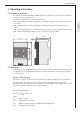
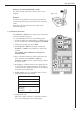
Preliminary check
The following checks must be performed at the base before
the mains voltage is switched on (housing with electronic
components should not be plugged in):
●
Insulation test on all cables (without consumers)
●
Resistance test (turn the rotary knob on each heater
clockwise as far as it will go)
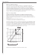
1. At Z1 and Z2 of the ELFAMATIC V 3000:
R= 176 Ω ... 100 kΩ
The measured resistance must not be less than 176 Ω.
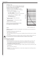
2. At W1 and W2 of the ELFAMATIC V 3000:
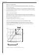
Atmospheric sensor
R = See diagram opposite
●
Switch on the mains voltage and measure
between L and N.
●
Simulate the LF release and measure the voltage
between LF and N.
●
Switch off the mains voltage.
Attach the top part of the housing to the base.
This completes the preliminary check.
2
-20 -15 -10 -5 0 5 10 15 20
3
4
5
6
7
8
9
10
11
12
13
14
15
Outside temperature (°C)
Resistance KΩ
2.4 Putting into operation
●
Switch on the voltage.
●
The output signal to the storage heaters is indicated by a signal lamp “ED” on the front of the
device. It depends on the outside temperature, the selected settings for E1 and E2, and the
selected ED system. Long ON times and short OFF times indicate a low charge; short ON times
and long OFF times indicate a high charge.
●
If the output signal is not displayed after approx. 1 minute, remove the device from the base and
check the fuse.
There is a spare fuse in the base.
Important: If the outside temperature has a value which corresponds to E1, the ED signal is 0 %,
i.e. the lamp remains OFF.
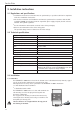
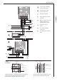
Sensor
Normally, the installation location of the atmospheric sensor should be selected according to the
following criteria:
●
Installation according to the illustration below
●
Min. height above ground: 2.5 m
●
The sensor should be mounted on the side of the building on which the main rooms to be heated
are located
●
The sensor must be mounted at a sufficient distance from doors, windows, exhaust-air ducts, etc.
The cable between the sensor and control unit must be suitable for mains voltage.
For the Fitter