INSTRUCTION BOOK FM 2500DD-A GB 325 88-8514 rev.
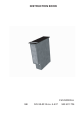
Your New Appliance Thank you for purchasing an AEG appliance. To enable you to use your new appliance efficiently and safely, please read this instruction book carefully before installing or using the appliance, and retain for future reference. Should the appliance be transferred to a new owner please ensure this instruction book is left with the appliance in order that the new owner can get to know the functions of the appliance and the relevant warnings.
Contents Page No. For the user Your New Appliance ........................................................................................ Safety information .......................................................................................... Product description ........................................................................................ Downdraught Extractor .......................................................................... Height positions ......................................
Contents Page No. For the electrician Unpacking ...................................................................................................... Technical data ................................................................................................ Installation........................................................................................................ Mounting ........................................................................................................
Safety Information Cleaning and Maintenance This downdraught extractor is designed for use in a normal domestic household. If used in any other way there could be a risk of an accident. For hygiene and safety reasons the downdraught extractor must be kept clean. In a worst case scenario, a clogged fat filter can ignite and burst into flames. Children Keep an eye on children when the downdraught extractor is in use. Never let children touch or play with the control knobs.
Installation The downdraught extractor may only be installed by an authorised electrician or someone approved by the manufacturer. Work carried out by unqualified persons can lead to personal injury and/or damage to property and may damage the downdraught extractor. During installation make sure the electricity cable is not pinched. Do not interfere with the downdraught extractor electrical parts.
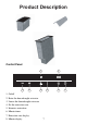
Product Description Control Panel 8 7 3 2 5 4 1. On/off 2. Raise the downdraught extractor 3. Lower the downdraught extractor 4. Set the extraction rate 5. Intensive extraction 6. Minute timer 7. Extraction rate display 8.
Downdraught Extractor The air is sucked in at the air dampers through the fat filter and is then blown via the extraction hose to the extraction duct and out into the open air. Height positions When installed beside electrical appliances, the downdraught extractor can be adjusted continuously from the centre position to the top position. When installed beside a gas appliance, the downdraught extractor can only extract in the top position.
How to use Downdraught Extractor Never leave the downdraught extractor unattended when deep-frying or melting fat or other easily ignited substances. Do not flambe food in the immediate proximity of a downdraught extractor that is switched on. This can cause fire. In the event of fire, the downdraught extractor must be switched off. Put out the fire with a lid. Never use water. Finger Touch The buttons have to be touched for at least 1 second before they are activated.
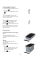
Downdraught Extractor 1. To turn the downdraught extractor on, press . 2. To select the height position, press . k m The downdraught extractor will move to middle position and switch on at extraction rate 1. To turn the downdraught extractor off, hold down until bottom position has been reached. Pressing will turn extraction off, but the downdraught extractor will remain where it is and not descend into the worktop.
The downdraught extractor will then stop rising automatically when the button is released or when top position is reached. Safety If the downdraught extractor is obstructed when raising, it will switch off automatically. Lowering 1. Press l. l , the downIf you keep pressing draught extractor will move steplessly between the top and bottom position. It will stop when you release the button. When the middle position is reached, the dampers retract and extraction is turned off.
Raising When the downdraught extractor is switched on. Select the height position within 10 seconds. 1. Press . The downdraught extractor will move to top position and switch on at extraction rate 1. The dampers will deploy on the way up. m Safety If the downdraught extractor is obstructed on the way up, it will switch off automatically. Lowering 1. Press l. Extraction will be turned off. The downdraught extractor will stop when you release the button.
Extraction rates The downdraught extractor can be set to three levels and intensive extraction. Level 1: 150 m³/h Level 2: 220 m³/h Level 3: 345 m³/h Intensive extraction: 480 m³/h Setting the extraction rate When the downdraught extractor is on, raised and at rate 1. < 1. Press one press = level 2 two presses = level 3 Adjusting the extraction rate The extraction rate can be adjusted by pressing . < Switching extraction off Press until the display shows 0.
Intensive extraction The downdraught extractor is on and raised. 1. Press b. The downdraught extractor will extract on intensive for 5 minutes. It will then return automatically to its last setting before intensive extraction was activated. If extraction was off before intensive extraction was activated, extraction will be turned off automatically after 5 minutes. Switching off intensive extraction You can switch intensive extraction off before the 5 minutes are up. Press b.
Time-controlled switching off You can set the downdraught extractor to switch off automatically at a later time. Time-controlled switching off can be set from 1 to 99 minutes. When the downdraught extractor is switched on and raised up. The suction strength is switched to speed 1, 2 or 3 (not to intensive suction). 1. Press the A button. By pressing once at a time, you set one minute at a time. If you hold the button down, you set 5 minutes at a time. If you pass 99 minutes, the time will display “00”.
When the time set has passed, suction strength is switched off. The downdraught extractor remains in the height position set. If you want to switch off the extraction rate before the time has passed, press the button until the display shows “00”. A Autostop If the downdraught extractor is left on by mistake, Autostop will turn extraction off automatically after 6 hours. The downdraught extractor will remain at the height position to which it was set.
Correct ventilation The extractor works best when there is low pressure in the kitchen. Therefore, the kitchen windows must be closed when the extractor is in operation. At the same time, it is a good idea to open a window in an adjacent room; see fig. Always start the extractor a few minutes before you start preparing food. Always continue to ventilate after you finish preparing food. Use intensive extraction with automatic stop or time-controlled switching off after 15 minutes.
Cleaning and maintenance Top cabinet The product should be kept clean for reasons of hygiene and safety. The top cabinet may become spattered with fat from frying. Never use metal cleaning pads, metal sponges, hard plastic sponges, scouring powder, soft soap or other abrasive and caustic cleaners. To clean 1. Switch the extractor on and raise it to the top position. 2. Lift the top cabinet off. 3. Wipe the top cabinet with a damp cloth and washing-up liquid or universal cleaner.
7. Assemble the filter, spring and top cabinet in reverse order. The filter must be completely dry before it is re-fitted in the extractor. 8. Reset the filter cleaning indicator by pressing and simultaneously for 3 seconds. "CL" will disappear from the display. If you clean the filter before the tablemounted cooker hood has been in use for 30 hours ("CL" has not appeared on the display), the filter cleaning indicator can be reset in the same way.
Unpacking Check that the appliance has no faults and is undamaged on delivery. Transport Damages Any damages resulting from a transport which you have not performed yourself must be communicated to the dealer within one week of receipt of the product. On the rating plate which is placed on the back of the product you will find the CE marking and the product’s serial number. Write the serial number on the front of present instruction book so it is easily accessible in the event of service.
Technical Data Model FM 2500DD-a: Product dimensions: Width: Depth: Height: 180 mm 520 mm 600 mm Installation dimensions: Width: Depth: Height: 160 mm 490 mm 647 mm Extraction rate: Level 1 Level 2 Level 3 Intensive extraction Extraction rate: Total output: Exhaust connection: Round pipe or hose: 150 m³/h 220 m³/h 345 m³/h 480 m³/h 310 W Ø 120 mm 21
Installation Electrical Installation Installation must be carried out by an authorised electrician or by a person authorised by the manufacturer. Work carried out by unqualified persons can lead to personal injury and/or damage to property and may spoil thedowndraught extractor. During installation make sure the cable is not pinched. Do not interfere with the electrical components of the downdraught extractor.
Connection Min. cable size: 0.75 mm² Cable type: HO5VV-F Installation must comply with any special requirements laid down by the local energy provider. The product must be connected via an external switch that disconnects all poles with a contact gap of at least 3 mm. (May be the main switch). L L2 L1 N PE Exhaust connection Exhaust connection: The connecting piece for the hose or pipe has a diameter of 120 mm. The exhaust hose must be at least 1 m long.
Installation beside a gas appliance If the downdraught extractor is installed beside a gas appliance, it must only be operated in top position and extract from the other side, i.e. the damper closest to the gas appliance must be closed permanently. This can be done as follows: 1. Modifying the electronic control system On the PCB cut the jumper labelled "JP01". The downdraught extractor can now only be operated in top position. 2.
3. Fitting the cover plate Fit the cover plate as follows: 1. Position the cover plate against the glass on the top cabinet. 2. Position the cover plate against the top cabinet. 3. Mark the four holes on the top cabinet, using the cover plate as a template. 4. Remove the cover plate and drill the four marked holes with a 3.2mm drill. 5. Take the backing off the tape. 6. Lay the cover plate against the top cabinet and press firmly into place. 7.
Mounting The unit may be mounted in any type of kitchen worktop with a thickness of 28 to 40 mm. Position It is advisable to position the downdraught extractor immediately next to the hob. If two or more hobs are being used, the downdraught extractor should be positioned between them so that optimum use can be made of its variable extraction direction.
Cutting Out When fitting this product: read the instructions on this page. When fitting this unit in conjunction with other units: read the instructions on the following page. For fitting this unit you will need a Phillips screwdriver and the fixing supplied (see fig.). Distance from wall: Min. 150 mm from flammable material Min. 50 mm from non-flammable material. 1. Saw a hole of the specified dimensions in the worktop, see “Technical data, installation dimensions”. 2.
Mounting more than one hob Distance to wall: Min. 150 mm (flammable material) Distance to wall: Min. 50 mm (non-flammable material) m 0m 49 Reinforcement beam Cutting out The measurement of the selected combination is calculated in the following way: Depth: 490 mm Width: 1. Calculate the sum of all units’ width. 2. Subtract 20 mm from the total width. Example: A hob of 720 mm + a downdraught of 180 mm + a gas hob of 360 mm. 1. 720+180+360= 1260 mm 2.
Mounting: When mounting several hobs together you must use a reinforcement beam between each hob as well as the silicone supplied with the hobs (see fig.) 1. Cut a hole of the calculated size in the table top 2. Place the individual hobs upside down on a mat. Take care that the top side is not scratched. 3. Mount the clamping fittings in the holes in the side of the base panels (see fig.) 4. Place the first hob in the hole. 5. Apply silicone to the two corners joining the next hob (see fig.
Overview of the outside width of the units 180 mm Downdraught 360 mm Glass ceramic hob with 2 cooking zones Gas hob with 2 burners Induction hob with 2 cooking zones Grill Grill / Fryer Wok 580 mm Glass ceramic hob with 4 cooking zones Gas hob with 4 burners 720 mm Glass ceramic hob with 4 cooking zones Gas hob with 4 burners Induction hob with 4 cooking zones 30
What to do if... If the appliance is not working correctly, please carry out the following checks before contacting your local AEG Service Force Centre. IMPORTANT: If you call out an engineer to a fault caused by incorrect use or installation, a charge will be made even if the appliance is under guarantee. Problems Remedy The downdraught extractor doesn’t work............. Check whether the extractor is switched on. Check the main fuse has not failed. Check the fuses for the extractor.
In-guarantee customers should ensure that the above checks have been made as the engineer will make a charge if the fault is not a mecanicas or electrical brakedown. Please note that it will be necessary to provide proof of purchase for any in-guarantee service calls.
Service and Spare Parts In the event of your appliance requiring service, or if you wish to purchase spare parts, contact your local AEG Service Force Centre by telephoning: 08705 929 929 Your call will automatically be routed to the Service Centre covering your post code area. For the address of your local Service Force Centre and further information about Service Force, please visit the website at www.serviceforce.co.
Customer Care For general enquires concerning your AEG appliance or for further information on AEG products, please contact our Customer Care Department at the address below or visit our website at www.aeg.co.
· · · · The appliance has not been serviced, maintained, repaired, taken apart or tampered with by any person not authorised by us. All service work under this guarantee must be undertaken by a Service Force Centre. Any appliance or defective part replaced shall become the Company’s property. This guarantee is in addition to your statutory and other legal rights. Home visits are made between 8.30am and 5.30pm Monday to Friday.
France Germany Italy Sweden UK Senlis Nürnberg Pordenone Stockholm Slough +33 (0)3 44 62 29 29 +49 (0)800 234 7378 +39 (0)800 117511 +46 (0)8 672 53 60 +44 (0)1753 219899 36