
Instruction manual

WARNING:
A) The pin arrangement for the ISO connectors depends on the type of vehicle you drive. Make sure to make the
prope connection to prevent damage to the unit.
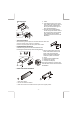
B) Make sure all the connectors are properly & tightly plug in before installation.
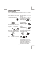
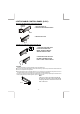
The default connection for wiring harness is as described in 1 below. If the ISO connectors pins are set as
described in 2 or 3 ,please make the correct connection as illustrated in 2 or 3 .
PLEASE MAKE SURE DOUBLE CHECK THE UNIT’S & VEHICLE’S ISO PIN ARRANGEMENT IS
MATCHING TO EACH OTHE BEFORE MAKING ANY WIRE CONNECTIONS!
1 Default setting. The A-7 pin (red ) of the vehicle’s ISO connector is linked to the ignition. And the A-4 pin (yellow)
is connected to the constant power supply ( battery ):
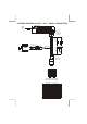
2 The A-7 pin ( red ) of the vehicle’s iso connector is connected to the constant power supply ( battery ) and the
A-4 pin ( yellow )is linked to the ignition, then please change the connections of the red & yellow wire by using the
small connector on these two wires as illustrated below :
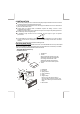
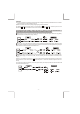
3 The A-4 pin ( Yellow ) of the vehicle’s iso is not connected to anything . Whicle the A-7 pin is connected to the
constant powe supply ( or both the A-7 ( Red ) and A-4 ( Yellow ) pins are connected to the constant power
supply ).
Warning : If you made the connection as 3 , the unit’s power will not be linked to the ignition key. For that reason,
always make sure to turn off the unit’s power when the ignition is turned off, otherwise it may drain the car’s
battery,
To link the unit’s power to the ignition, connect the ignition cable ( Acc--Red ) to a power source that can be turned
on and off with the ignition key.
- 7 -