
User's Manual


10
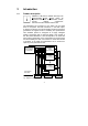
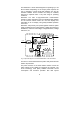
An integrated, manually operated bypass unit ensures an
uninterrupted supply to the connected loads in the case of
maintenance and/or service work. The internal electronic part
(with the exception of the metal-clad manual bypass) can be
disconnected via the mains input miniature circuit breakers.
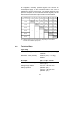
Fig.: Table showing the level of redundancy depending on the installed
modules and available output power
2.2 Technical Data
Type rating
PROTECT 1.M (system) max. 24 kVA (cos ϕ = 0.7 lag.)
16800 W
PROTECT 1.040 (module) 4000 VA (cos ϕ = 0.7 lag.)
2800 W
UPS input 3ph~ or 1ph~ / N / PE
Rated connection voltage 400 V / 230 Vac (3ph~) or
230 V (1ph~)
Voltage range without 277 Vac – 520 Vac ±3%
battery operation (Rectifier 3ph~)
160 Vac – 300 Vac ±3%
(Rectifier 1ph~)
no
redundancy
n+1
(4 kVA)
n+2
(8 kVA)
n+3
(12 kVA)
n+4
(16 kVA)
n+5
(20 kVA)
6
modules
5
modules
4
modules
3
modules
2
modules
1
module
Number of
UPS modules
Load
---
no
redundancy
- - -
20 kV
A
n+1
(4 kVA)
no
redundancy
- - -
16 kV
A
n+2
(8 kVA)
n+1
(4 kVA)
no
redundancy
- --
12 kV
A
n+3
(12 kVA)
n+2
(8 kVA)
n+1
(4 kVA)
no
redundancy
---
8
kV
A
n+4
(16 kVA)
n+3
(12 kVA)
n+2
(8 kVA)
n+1
(4 kVA)
no
redundancy
4 kV
A
2
4
kV
A