
Operation Manual


Protect PV.250 Operating Instructions
Page 5 of 51 80000027023 BAL, en
1.1 Technology
Due to the utilisation of high-performance electronic components,
the Protect PV.250 boasts a very high degree of operational reli-
ability, is extremely efficient and is characterised by its versatility in
communicating with other systems by means of interfaces.
The entire control electronics of the Protect PV.250 are based on
microcomputer assemblies. The fact that the various assemblies
are logically integrated and linked into the overall system means
that unit properties can be defined by making unit-specific parame-
ter settings in the software.
Information is exchanged between the individual modules using
the CAN bus (Controller Area Network). This CAN bus features
high interference immunity and is used in a wide variety of indus-
trial applications.
DC
(PV modules)
Q4
=
~
~
~
K7
Q26
AC (Incoming mains)
Kommunikation
Display
M
Control unit power supply
AC mains 2
Control unit
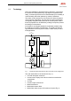
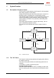
Fig. 1 Functional principle of the Protect PV.250 for connection to a low-voltage mains
The main assemblies of the inverter are (Fig. 1):
• DC load interrupter switch Q4
• Inverter stack, display and control unit with communication
components
• AC filter
• Inverter output contactor K7
• Mains transformer
• Mains disconnector Q26
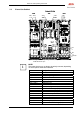
• Mains filter choke (only on MV version) L26 (see Fig. 2)