
Operation Manual


Protect PV.250 Operating Instructions
Page 6 of 51 80000027023 BAL, en
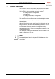
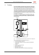
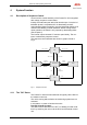
Fig. 1 illustrates the principle of the Protect PV.250.
The PV cells supply the INV stack with DC voltage via DC load in-
terrupter switch Q4. The INV stack converts this DC voltage into a
3-phase AC voltage. A sinusoidal current is fed into the mains via
the AC filter, contactor K7 and the mains transformer.
Mains disconnector Q26 and load interrupter switch Q4 are pro-
vided for isolating the inverter in the event of unit faults or when
maintenance needs to be performed on the unit.
CAUTION:
Potentially fatal voltages are present at the terminals on the
Protect PV.250.
The control unit is supplied with power from the AC mains or, op-
tionally, from a second AC mains.
DC
(PV modules)
Q4
=
~
~
~
K7
Q26
AC (Incoming mains)
Control unit
Kommunikation
Display
M
Control unit power supply
AC mains 2
L26
Fig. 2 Functional principle of the Protect PV.250 for connection to a medium-
voltage mains