
Operation Manual


Protect PV.250 Operating Instructions
Page 8 of 51 80000027023 BAL, en
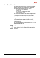
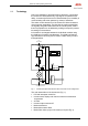
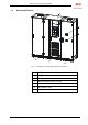
1.3 View of the Cabinet
+DCD
+INV
Protect PV.
2
5
0
+ACD
X:301
X:103
X:101
X:202
X:203
X:200
X:201
X:303
X3:U,V,W
X11
X13
Q4.1
K7
A1
A17
A91.2
A91.1
A27
A
29.1
A12
A20
L26
L4
X41
C7
A115.1
A115.2
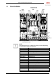
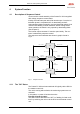
Fig. 4 Arrangement of the operating elements, components and individual
PCBs with doors open
i
NOTE:
The image above may not always be strictly accurate, depending
on which options have been selected.
Item Designation
A1 Power stack 250 kW
A115.1-A115.2 CAN I/O
A12 Remote signalling
A17 PV INV interface
A20 Partner operation
A27 COM server
A29.1-A29.2 Multicom CCC
A30 Modem PV
A91.1,A91.2 Fan monitoring
F41 Input fuse DC voltage (DC)
K7 Inverter output contactor
L26 Mains filter choke (only on MV version)
Q4.1 DC load interrupter switch
X3 Inverter output/mains connection
X11 Power supply mains 2
X13 230 VAC client terminal
X200-X203 Terminal layout, cabinet connection
X41 Input terminals DC voltage (DC)