RTi 102 E, RTi 103 EP Deutsch Integrierbare Raumtemperaturregler für Wärmespeicher WSP 1210 F bis WSP 4810 F, WSP 3510 N und WSP 5010 N Gebrauchs- und Montageanweisung RTi 102 E, RTi 103 EP English Integrated Room Temperature Regulator for Electric Storage Heaters WSP 1210 F to WSP 4810 F, WSP 3510 N and WSP 5010 N Operating and Installation instructions RTi 102 E, RTi 103 EP Français Thermostat d’ambiance intégré pour accumulateurs de chaleur WSP 1210 F à WSP 4810 F, WSP 3510 N et WSP 5010 N Notice
Inhaltsverzeichnis 1. Gebrauchsanweisung Für den Benutzer 1.1 Arbeitsweise ____________________________________________________________________ 3 2. Montageanweisung Für den Installateur 2.1 2.2 2.3 2.4 2.
Für den Benutzer Deutsch 1. Gebrauchsanweisung RTi 102 E Bei dem Raumtemperaturregler RTi 102 E handelt es sich um einen elektronischen 2-Punktregler; d. h., die Gebläse des Wärmespeichers werden eingeschaltet, mit konstanter Drehzahl betrieben und wieder abgeschaltet. RTi 103 EP Bei dem Raumtemperaturregler RTi 103 EP handelt es sich um einen elektronischen Proportionalregler; d. h., die Drehzahl der Wärmespeicher-Gebläsemotoren wird vom RTi 103 EP stufenlos dem Wärmebedarf angepasst.
Für den Installateur 2. Montageanweisung Der Einbau des Raumtemperaturreglers muss von einem zugelassenen Fachmann unter Beachtung dieser Gebrauchs- und Montageanweisung sowie der Gebrauchs- und Montageanweisung des Wärmespeichers vorgenommen werden. Alle elektrischen Anschluss- und Installationsarbeiten sind nach den VDE-Bestimmungen 0100, den Vorschriften des zuständigen EVU sowie den entsprechenden nationalen und regionalen Vorschriften auszuführen. 2.
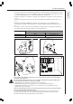
Für den Installateur Deutsch • 6-polige Steckverbinder des Entladereglers (A2 siehe Schaltplan) hinter dem Winkelblech entlang nach oben führen, von oben in die Steckplätze TA" bis N" der Anschlussklemme X2 stecken und " " eindrücken). verschrauben (Kabelbaum in die vorhandenen Kabelhalter • Entladeregler (6) in die oberhalb des Aufladereglers angebrachten Langlöcher stecken und einrasten. • Anschlussleitung des Potentiometers auf den Steckplatz X21 des Raumtemperaturreglers stekken.
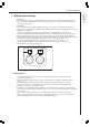
Für den Installateur 2.4 Funktionsprüfung EIN/AUS-Schalter in Stellung Entladung bringen. Temperatur-Wählknopf drehen, bis Gebläse vom Wärmespeicherteil einschaltet. Schaltet das Gebläse nicht ein, so sind die Betriebs- und Störanzeigen am Auf- und Entladeregler zu beachten. 2.4.1 Betriebs- und Störanzeige am Aufladeregler LED leuchtet "grün" ⇒ keine Störung der Aufladeregler arbeitet einwandfrei.
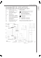
Für den Installateur A1: B1: E1 - E6: F1: F2: K1: M1 - M3: N4: N5: R1: V4: X1: X2: X3: X16: X17: Elektronischer Aufladeregler Kerntemperaturfühler - Aufladung Heizkörper (Speicher) Sicherheits-Temperaturbegrenzer Sicherung (250 V 2A träge) Thermorelais Gebläse Entladung Temperaturbegrenzer - Aufladung Temperaturbegrenzer - Entladung Einsteller - Aufladung (Wählknopf) Kontrollleuchte Betrieb Notbetrieb Netzanschlussklemme Anschlussklemme DC-Anschlussklemme 0,91 - 1,43 V Steuersignalanpassung 4-stufig Leist
Für den Installateur Stromlaufplan WSP 1210 - 4810 F mit RTi 103 EP Stromlaufplan WSP 3510 und 5010 N mit RTi 103 EP A1: B1: E1 - E6: F1: F2: K1: M1 - M3: N4: N5: R1: V4: X1: X2: X3: X16: X17: Elektronischer Aufladeregler Kerntemperaturfühler - Aufladung Heizkörper (Speicher) Sicherheits-Temperaturbegrenzer Sicherung (250 V 2A träge) Thermorelais Gebläse Entladung Temperaturbegrenzer - Aufladung Temperaturbegrenzer - Entladung Einsteller - Aufladung (Wählknopf) Kontrollleuchte Betrieb Notbetrieb Netzansch
3. Kundendienst und Garantie Deutsch Kundendienst und Garantie Stand: 10/06 / Sollte einmal eine Störung an einem der Produkte auftreten, stehen wir Ihnen natürlich mit Rat und Tat zur Seite. Rufen Sie uns einfach unter nachfolgender Service-Nummer an: 01803 70 20 20 (0,09 _/min; Stand 11/06) oder schreiben uns: AEG Haustechnik - Kundendienst - Fürstenberger Straße 77, 37603 Holzminden E-Mail: info@aeg-haustechnik.de Telefax-Nr.
Kundendienst und Garantie Inanspruchnahme der Garantie Garantieansprüche sind vor Ablauf der Garantiezeit, innerhalb von zwei Wochen nachdem der Mangel erkannt wurde, unter Angabe des vom Kunden festgestellten Fehlers des Gerätes und des Zeitpunktes seiner Feststellung bei AEG Haustechnik anzumelden. Als Garantienachweis ist die vom Verkäufer des Gerätes ausgefüllte Garantieurkunde, die Rechnung oder ein sonstiger datierter Kaufnachweis beizufügen.
Table of Contents 1. Operating instructions For the user 1.1 Functional principle _____________________________________________________________ 12 English 2. Installation instructions For the fitter 2.1 Technical data _________________________________________________________________ 13 2.2 Packing unit ___________________________________________________________________ 13 2.3 Installation ____________________________________________________________________ 13 2.
For the Fitter 1. Operating Instructions RTi 102 E The room temperature regulator RTi 102 E is an electronic 2-position controller, i.e. the fans of the storage heater are switched on, operated at constant speed and switched off again. RTi 103 EP The room temperature regulator RTi 103 EP is an electronic proportional controller, i.e. the speed of the storage heater’s fan motors is adapted to the heat requirement continuously by the RTi 103 EP.
For the User 2. Installation instructions The room temperature regulator must be fitted by an authorised specialist under consideration of these operation and installation instructions and the operating and installation instructions of the storage heater. All electrical connection and installation work must be performed in accordance with the VDE regulations 0100, the regulations of the electricity supply company responsible and the pertinent national and regional regulations. 2.
For the Fitter • Feed the 6-pole connector of the discharge control unit (A2 see circuit diagram) up along the back of the angle plate into the slots "TA" to „N“ of the terminal block X2 from above and screw (press cable harness into the existing cable straps). • Plug and snap in the discharge control unit (6) in the elongated holes above the charging control unit. • Plug the connecting lead of the potentiometer into the slot X21 of the room temperature regulator.
For the Fitter 2.4 Function Test Move the ON/OFF switch to the discharge position Turn the temperature selector knob until the fan in the storage heater unit switches on. If the fan does not switch on, the operating and fault indicators on the charging and discharge control unit must be observed. LED lights „red“ ⇒ Fault a) Selector knob for charging (R1) and/or brick sensor (B1) defective or not connected. b) Plug-in bridge for reduction of charging factor on the charging control unit.
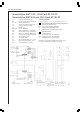
For the Fitter Circuit diagram WSP 1210 - 4810 F with RTi 102 E Circuit diagram WSP 3510 and 5010 N with RTi 102 E A1: B1: E1 - E6: F1: F2: K1: M1 - M3: N4: N5: R1: V4: X1: X2: X3: X16: X17: Electronic charging control unit Brick temperature sensor - charging Heating element (storage heater) Safety temperature limiter Fuse (250 V / 2 A slow-blow) Thermal relay Fan discharge Temperature limiter - charging Temperature limiter - discharging Adjuster – charging (selector knob) Pilot lamp operation emergency o
For the Fitter Circuit diagram WSP 1210 - 4810 F with RTi 103 EP Circuit diagram WSP 3510 and 5010 N with RTi 103 EP Electronic charging control unit Brick temperature sensor - charging Heating element (storage heater) Safety temperature limiter Fuse (250 V / 2 A slow-blow) Thermal relay Fan discharge Temperature limiter - charging Temperature limiter - discharging Adjuster – charging (selector knob) Pilot lamp operation emergency operation Mains terminal Terminal DC terminal 0.91 – 1.
Environment and recycling 3 Guarantee For guarantee please refer to the respective terms and conditions of supply for your country. The installation, electrical connection and first operation of this appliance should be carried out by a qualified installer. The company does not accept liability for failure of any goods supplied which are not installed in accordance with the manufacturer's instructions. 3.
Sommaire 1. Notice d’utilisation A l’intention de l’utilisateur 1.1 Fonctionnement _______________________________________________________________ 20 2. Notice de montage A l’intention de l’installateur 2.1 2.2 2.3 2.4 2.
A l’intention de l’utilisateur 1. Notice d’utilisation RTi 102 E Le thermostat d’ambiance RTi 102 E est un régulateur électronique à deux positions : les ventilateurs de l’accumulateur de chaleur sont mises en route, tournent à vitesse constante puis sont coupées. RTi 101 EP Le thermostat d’ambiance RTi 103 EP est un régulateur électronique proportionnel : la vitesse des moteurs de ventilateurs de l’accumulateur de chaleur est ajustée aux besoins en continu par le RTi 103 EP.
A l’intention de l’installateur 2. Notice de montage Le montage du thermostat d’ambiance doit être effectué par un spécialiste agréé. Celui-ci tiendra compte du présent mode d’emploi et des instructions de montage ainsi que du mode d’emploi et des instructions de montage de l’accumulateur de chaleur.
A l’intention de l’installateur • Faire passer le connecteur 6 pôles du régulateur de décharge (A2 voir schéma des connexions) derrière la tôle. L’enficher par le haut dans les bornes « TA » à « N » du bornier X2 et le visser (enfoncer le faisceau dans le porte-câble). • Enfoncer le régulateur de décharge (6) dans les trous oblongs placés au dessus du régulateur de décharge et le verrouiller en position. • Enficher le câble de liaison du potentiomètre sur la borne X21 du thermostat d’ambiance.
A l’intention de l’installateur 2.4 Contrôle de fonctionnement Amener l’interrupteur de MARCHE/ARRET en position décharge. Tourner le sélecteur de température jusqu’à ce que la soufflante de l’accumulateur de chaleur se mette en route. Si la soufflante ne se déclenche pas, suivre les indications de dysfonctionnement du régulateur de charge et de décharge. 2.4.
A l’intention de l’installateur Schéma électrique WSP 1210 - 4810 F avec RTi 102 E Schéma électrique WSP 3510 et 5010 N avec RTi 102 E A1: B1: E1 - E6: F1: F2: K1: M1 - M3: N4: N5: R1: V4: X1: X2: X3: X16: X17: Régulateur électronique de charge Capteur de température interne - Charge Elément chauffant (accumulateur) Limiteur de température Fusible (250 V 2A à action retardée) Relais thermique Soufflante de décharge Limiteur de température - Charge Limiteur de température – Décharge Régulateur – Charge (sé
A l’intention de l’installateur Schéma électrique WSP 1210 - 4810 F avec RTi 103 EP Schéma électrique WSP 3510 et 5010 N avec RTi 103 EP A1: B1: E1 - E6: F1: F2: K1: M1 - M3: N4: N5: R1: V4: X1: X2: X3: X16: X17: Régulateur électronique de charge Capteur de température interne - Charge Elément chauffant (accumulateur) Limiteur de température Fusible (250 V 2A à action retardée) Relais thermique Soufflante de décharge Limiteur de température - Charge Limiteur de température – Décharge Régulateur – Charge (
Environnement et recyclage 3 Garantie La garantie est à faire valoir dans le pays où l'appareil a été acheté. A cette fin, veuillez prendre contact avec la filiale AEG concernée, à défaut l'importateur agréé. Le montage, les raccordements, la maintenance ainsi que la première mise en service sont à réaliser par un installateur qualifié.
Inhoudsopgave 1. Gebruiksaanwijzing Voor de gebruiker 1.1 Werkwijze ____________________________________________________________________ 28 2. Montagehandleiding Voor de installateur 2.1 2.2 2.3 2.4 2.
Voor de installateur 1. Gebruiksaanwijzing RTi 102 E Bij de thermostaat RTi 102 E gaat het om een elektronische 2-punts regelaar, d.w.z. dat de ventilatoren van de warmteaccumulatoren worden ingeschakeld, met een constant toerental draaien en weer worden uitgeschakeld. RTi 103 EP Bij de thermostaat RTi 103 EP gaat het om een elektronische proportionele regelaar, d.w.z. dat het toerental van de ventilatormotoren van de warmteaccumulatoren door de Rti 103 EP traploos aan de warmtebehoefte wordt aangepast.
Voor de gebruiker 2. Montagehandleiding De inbouw van de thermostaat moet worden uitgevoerd door een daartoe bevoegde vakman met inachtneming van de gebruiks- en montagehandleiding van zowel de thermostaat als de warmteaccumulator. Alle elektrische aansluit- en installatiewerkzaamheden dienen te worden uitgevoerd conform de VDE-bepalingen 0100, de voorschriften van de verantwoordelijke elektriciteitsbedrijven en de betreffende nationale en regionale voorschriften. 2.
Voor de installateur • De 6-polige stekkerverbinding van de ontlaadregelaar (A2 zie schakelschema) achter de bevestigingsplaat langs naar boven geleiden, van bovenaf in de stekker „TA“ tot „N“ van de aansluitklem X2 steken en vastdraaien (kabelboom in de aanwezige kabelhouder drukken). • De ontlaadregelaar (6) in de boven de oplaadregelaar aangebrachte slobgaten steken en vastzetten. • De aansluitleiding van de potmeter op de stekkerplaats X21 van de thermostaat steken.
Voor de installateur 2.4 Functiecontrole Zet de AAN/UIT-schakelaar in de stand ontlading Vervolgens de temperatuurkeuzeschakelaar draaien, totdat de ventilator van de warmteaccumulator wordt ingeschakeld. Neem, wanneer de ventilator niet wordt ingeschakeld, de bedrijfs- en foutmeldingen op de op- en ontlaadregelaar in acht. 2.4.1 Bedrijfs- en storingsmeldingen op de oplaadregelaar ⇒ geen storing LED brandt „groen“ de oplaadregelaar werkt zonder problemen.
Voor de installateur Schakelschema WSP 1210 - 4810 F met RTi 102 E Schakelschema WSP 3510 en 5010 N met RTi 102 E A1: B1: E1 - E6: F1: F2: K1: M1 - M3: N4: N5: R1: V4: X1: X2: X3: X16: X17: Elektronische oplaadregelaar Kerntemperatuurvoeler - opladen Verwarmingselement (accumulator) Veiligheidstemperatuurbegrenzer zekering (250V 2A traag) Thermorelais Ventilator ontladen Temperatuurbegrenzer - opladen Temperatuurbegrenzer - ontladen Regelaar – opladen (keuzeschakelaar) Controlelampje werking noodwerking N
Voor de installateur Schakelschema WSP 1210 - 4810 F met RTi 103 EP Schakelschema WSP 3510 en 5010 N met RTi 103 EP A1: B1: E1 - E6: F1: F2: K1: M1 - M3: N4: N5: R1: V4: X1: X2: X3: X16: X17: Elektronische oplaadregelaar Kerntemperatuurvoeler - opladen Verwarmingselement (accumulator) Veiligheidstemperatuurbegrenzer zekering (250V 2A traag) Thermorelais Ventilator ontladen Temperatuurbegrenzer - opladen Temperatuurbegrenzer - ontladen Regelaar – opladen (keuzeschakelaar) Controlelampje werking noodwerking
Milieu en recycling 3 Garantie Aanspraak op garantie bestaat uitsluitend in het land waar het materiaal gekocht is. U dient zich te wenden tot de vestiging van AEG of de importeur hiervan in het betreffende land. De montage, de elektrische installatie, het onderhoud en de eerste inbedrijfname mag uitsluitend worden uitgevoerd door een gekwalificeerd persoon.
Notizen · Notes · Notes · Notices 35
Adressen und Kontakte Regionen EHT Haustechnik GmbH Markenvertrieb AEG Gutenstetter Straße 10 90449 Nürnberg info@eht-haustechnik.de www.aeg-haustechnik.de Tel. 0 18 03 / 91 13 23 Fax 09 11 / 96 56 - 44 4 AEG Kundendienst Kundendienstzentrale Holzminden Fürstenberger Str. 77 37603 Holzminden Briefanschrift 37601 Holzminden Der Kundendienst und Ersatzteilverkauf ist in der Zeit von Montag bis Donnerstag von 7.15 bis 18.00 Uhr und Freitag von 7.15 bis 17.00 Uhr, auch unter den nachfolgenden Telefon- bzw.