OPERATING INSTRUCTION EXTERNAL BYPASS SWITCH MBS 2000 MBS 3000 2
1 General The external, manually operated bypass unit is an option for the PROTECT B., C. and C.R UPS series. It is used for isolating the UPS, for example for maintenance purposes, whilst the connected loads continue to be supplied without interruption. Furthermore, an additional switch setting permits UPS test operation.
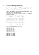
Installation (mechanical) Type MBS 2000 PROTECT B. 750 / B. 1000 PROTECT B. 1500 / B. 2000 PROTECT C. 1000 / C. 1000R PROTECT C. 2000 Example: PROTECT C. 1000 with MBS 2000 Attach the external bypass to tower units with using the four adhesive pads on the side of the UPS housing as shown in the adjacent figure. Type MBS 3000 PROTECT B. 3000 PROTECT C. 3000 / C.
The gluing points must be dry and free from grease. The adhesive pads do not develop their full strength until after a curing time of approx. 24 hours. Do not apply any mechanical load to the external bypass unit during this time. Press the unit on firmly at the start. PROTECT C.1000R / C.2000R / C.3000R / B. Rack version For use in a rack, use the four screws supplied with the bypass unit to attach the two supplied retaining brackets to the sides of the unit.
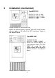
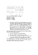
4 Connection (electrical) If you have already taken the UPS into operation then switch it off as the first step. Now disconnect the UPS from the mains by disconnecting the mains connector. Before you perform the installation described below, make sure that none of the cables are live. Make sure that the external bypass switch is in its default position "NORMAL". Rear view of MBS 2000 for unit types: PROTECT B. 750 PROTECT B. 1000 PROTECT B. 1500 PROTECT B. 2000 PROTECT C. 1000 PROTECT C. 1000R PROTECT C.
Rear view of MBS 3000 for unit types: PROTECT B. 3000 PROTECT C. 3000 PROTECT C. 3000R 1. Connect the input of the external bypass to the mains connection cable provided with the UPS and plug the mains connector into a suitable shockproof socket. In particular in the case of high-capacity types, ensure that the fusing in your sub-distribution is adequately dimensioned: The 3 kVA system, for example, requires its own connection with a 16 A fuse.
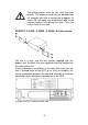
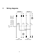
Wiring diagrams ( NORMAL ) ( TEST ) ( BYPASS ) Service position Manual bypass UPS output 230V/N/PE~50/60Hz UPS operation 5 UPS input 230V/N/PE~50/60Hz L1 N PE L1 N PE L1 N PE L1 N PE Loads 230V/N/PE~50/60Hz 8 Mains 230V/N/PE~50/60Hz
Guarantee Certificate Type: ……………….……………………………….................... Serial-No: ………..……….……………………………………… Date of Purchase: ………......……..…………………………… Trading stamp /Signature Specifications are subject to change without notice.