
Operating instructions


76
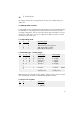
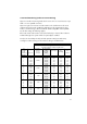
3.1.4 Analog input
S1-
7 8 Signal level Input resistance
0 0 0 - 10V 88k
1 0 undefined undefined
0 1 0 - 5V 44k 44 (e.g for set point potentiometer)
1 1 0 - 20mA 250
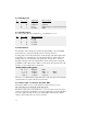
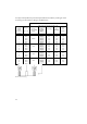
3.1.5 Analog output
The analog output allows the display of U
rms
or P (H RLP) as in 3.1.2
S1-
9 10 Output signal level
0 1 0 - 10V
1 1 2 - 10V
0 0 0 - 20mA
1 0 4 - 20mA
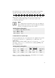
3.2 Potentiometer
The description of the settings proceeds from the upper (R201) to the lower (R205)
potentiometer. A 19 mm potis with 20 revolutions is being referred to.
A setting guide exists for all potentiometers via the analog output (X2:9 against X2:5
ground). If a poti is changed, this is recognised by the Thyro-A. It then switches the
analog output over so that instead of the actual value, the poti value is read out.
During the setting procedure the red LEDs flicker. As the analog output is designed
for 0-20mA / 10V, 10mA (=5V) = 100% is set. This allows the set points to be read
directly or in a percentage of the nominal value:
Analog output (setting guide)
10 V or 20.0mA = 200%
5 V or 10.0mA = 100% or 100°el.
2.5 V or 5.0mA = 50% or 50°el.
1.25V or 2.5mA = 25% etc.
If the poti is not substantially changed within 30 seconds, the Thyro-A automatically
switches back to the output of the chosen actual value.
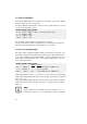
3.2.1 Phase angle 1. half wave operation TAKT
Potentiometer R201 serves to set the transformer load. At works it is set at
60° el with Thyro-A 1A and at 90° el with Thyro-A 2A.
Transformer loads with a nominal induction 1.2 T, as well as wound core and to-
roidal core transformers optimization is necessary. With Thyro-A 1A generally 80°el
turn (to the right), with Thyro-A 2A turn at smaller angles (to the left). An optimal
setting is achieved when the rush current is minimal.