
Operating instructions


79
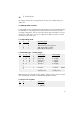
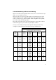
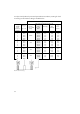
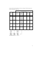
For Thyro-A 1A and Thyro-A 2A (load with separate neutral point without N)
a setting for load monitoring can be made according to the table below:
Thyro-A 1A
Thyro-A 2A
load with separate neutral point without N
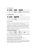
e.g.
parallel
load
resistances
Number
I
load nom.
/
I
type contr.
Resistance
increase
in case
of fault
Recommended
setting
for poti
R205
X2.9 [V]
X2.9
[0-20mA]
ca.
Revo-
lutions
1 100% 50.0% 5.0 10.0 8.5
1 80% 40.0% 4.0 8.0 7.0
1 60% Infinite 30.0% 3.0 6.0 6.0
1 40% 20.0% 2.0 4.0 4.5
1 20% 10.0% 1.0 2.0 2.5
2 100% 75.0% 7.5 15.0 12.0
2 80% 60.0% 6.0 12.0 9.5
2 60% 100% 45.0% 4.5 9.0 7.5
2 40% 30.0% 3.0 6.0 6.0
2 20% 15.0% 1.5 3.0 3.5
3 100% 83.3% 8.3 16.7 13.0
3 80% 66.7% 6.7 13.3 10.5
3 60%
50%
50.0% 5.0 10.0 8.5
3 40% 33.3% 3.3 6.7 6.0
4 100% 87.5% 8.8 17.5 13.5
4 80% 70.0% 7.0 14.0 11.5
4 60%
33%
52.5% 5.3 10.5 9.0
4 40% 35.0% 3.5 7.0 6.0
5 100% 90.0% 9.0 18.0 14.0
5 80% 72.0% 7.2 14.4 11.5
5 60%
25%
54.0% 5.4 10.8 9.0
5 40% 36.0% 3.6 7.2 6.5
Tab. 2a Load monitoring
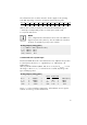
3.2.5 Load monitoring (undercurrent monitoring)
Thyro-A is suited for monitoring loads which consist of one or several resistors in pa-
rallel or in series parallel connection.
Thyro-A recognises an increase in load resistance. The load monitor works as an
undercurrent monitor and is suitable for application in all operating and control
modes. Load monitoring is delivered with the default setting OFF = left stop R205.
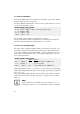
For all other settings the following applies:
If the load current undercuts the set level, the fault relay is released. The incident is
indicated through a bus system which can optionally be installed.