
Operating instructions


83
➜
4. External connections
4.1 Power supply for Thyro-A
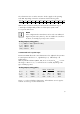
Connecting the power supply is carried out as shown in the figures and technical
data. With Thyro-A 2A a right rotational field in the power circuit is required.
4.2 Power supply for the control device
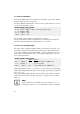
The control device is supplied directly from the power section (terminals U1, X1.1
and X1.2). This voltage also serves as mains synchronization. The mains connection
is equipped for input voltages of U
Nnom
-15% to +10% and nominal frequencies
of 47Hz to 63Hz. Both terminals (X1.1 and X1.2 1.5mm
2
grid 3.81) are internally
bridged. If a phase is connected to X1, a fused connection is necessary
(figs. 3,7).
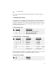
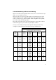
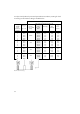
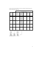
Description LEDs Relay K1 Description
Frequency fault PULSE INHIBIT blinks open Outside 47Hz to 63 Hz
when switching on or
SYNC fault PULSE INHIBIT blinks open Zero crossing outside
permissible tolerance range
in operation
Temperature monitoring LOAD FAULT blinks open Temp. monitoring responded
(control board or control
section)
Load fault LOAD FAULT on open Load fault: none or under current
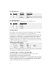
Flash values invalid 2 red LEDs open Controller fault
Correction values invalid synchron. blinks
Undervoltage open Mains fault
Overvoltage -- Mains fault
Pulse lock active PULSE INHIBIT closed Bridge X2: 1.2
opened
U-limitation 2 red LEDs blink none U limit value exceeded
slowly, alternatively
I-limitation 2 red LEDs blink none I limit value exceeded
slowly, alternatively
P-limitation (H RLP) 2 red LEDs blink none P limit value exceeded
slowly, alternatively
Tab 3 Allocation of message register
3.3 Diagnosis / status indications
Faults can occur in the load circuit and in the controller itself or from the mains.
Diagnosis of unexpected operating behaviour is performed by LEDs on the front
panel of the control device.