
Operating instructions

95
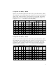
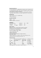
The default settings of the potentiometer can be taken from the following
table.
Tab 5 Default values potentiometer
Setting
Chapter
No.
DefaultPhase angle 1. half wave
Set point value input control end
Current limit
Load monitoring
act. Setting
R201
Thyro-A 1A: 60°el
Thyro-A 2A: 90°el
3.2.1
3.2.2
3.2.3
3.2.5
U-Control: U
Type
+10%
I
Type
OFF
R202
R203
R205
All standard settings should be checked by the user as a matter of course and
adjusted to the operating conditions (e.g. operating mode, control mode, limits,
monitoring, control characteristics, actual value output, fault indications etc.)
ATTENTION
Apart from the load and current supply to X1.1, certain control signals
must be connected too. The following signals are essential for opera-
ting the device:
• Set point (terminal 4 or by bus option)
• Pulse lock (on ground, on terminal 1,2; jumper)
If the pulse lock jumper is not connected, the device is in a locked state and will not
operate. Communication via interface is still possible. Further details on the pulse
lock are described in the chapter of the same name.
ATTENTION
Heat sinks and neighbouring plastic parts are hot during
operation!
8.3 Service
The devices delivered have been produced under quality standard ISO 9001.
Should nevertheless faults or problems occur, our 24-hour service hotline is at your
service: Tel. +49(0)2902 / 763-100.