
User manual


- 49 -
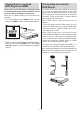
Connect the PC cable between the PC INPUT on the TV and the PC output on your PC.
Note: You can use YPbPr to VGA cable(not supplied) to enable YPbPr signal via PC input.
SPDIF Out4. outputs audio signals of the currently watched source.
Use an SPDIF cable to transfer audio signals to a device that has SPDIF input.
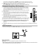
Viewing the Connections - Side Connectors
CI slot is used for inserting a conditional access module (CAM) and viewing 1.
card. The viewing card allows you to view all the channels that you subscribe
to. For more information, see “Conditional Access” section.
NOTE: The CAM is inserted with the gold contacts and label facing rearwards.
Side USB input.2.
Video Input is used for connecting video signals of external devices.Connect 3.
the video cable between the VIDEO IN socket on the TV and the VIDEO OUT
jack on your device.
Audio Inputs are used for connecting audio signals of external devices. 4.
Connect the audio cable between the AUDIO INPUTS on the TV and the
AUDIO OUTPUT jacks on your device.
Note: If you connect a device to the TV via the VIDEO INPUT, you should also connect
your device with an audio cable to the AUDIO INPUTS of the TV to enable audio.
Headphone jack is used for connecting an external headphone to the system. 5.
Connect to the HEADPHONE jack to listen to the TV from headphones
(optional).
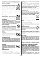
The Control switch allows you to control the Volume/ Programme/ Source and Standby-On functions of 6.
the TV.
Aerial Connection
Connect the aerial plug to the • AERIAL INPUT (ANT) socket located at the rear of the TV.
HDMI 1
SPDIF
Coax.OUT
Power Connection
IMPORTANT: The TV set is designed to operate on 220-240V AC, 50 Hz.
After unpacking, allow the TV set to reach the ambient room temperature before you connect the set to the •
mains. Plug the power cable to the mains socket outlet.
MODE
o
5Vdc-Max500mA
02_MB62_[GB]_(01-TV)_IDTV_BRONZE19_1900UK_19742W_10074722.indd 49 16.08.2011 16:33:34