Operating Instructions "UniVert 2" inverter and SBS option AEG Power Supply Systems GmbH Department: PPSD TED Name: Gleitsmann/Schenuit Revision: 01 Date: 06.08.
"UniVert 2" inverter Notes on these Operating Instructions Duty to Provide Information These operating instructions must be read carefully by all persons working with or on the inverter system prior to installation and initial start-up. These operating instructions are a composite part of the inverter system. The operator of this unit is obliged to make these operating instructions available to all personnel transporting or starting up units, or performing maintenance or any other work on the unit.
"UniVert 2" inverter Abbreviations The following abbreviations are used in these instructions: INV = Inverter SBS = Static Bypass Switch DOU = Display and Operation Unit SMPS = Switch Mode Power Supply PSM = Power Supply Monitoring Hotline Do you have any suggestions for improving these operating instructions? Do you have any questions on any of the subjects dealt with in these operating instructions? Our service department is available on the hotline number given below: AEG Power Supply Systems GmbH Em
"UniVert 2" inverter Table of Contents Notes on these Operating Instructions ...........................................2 1 1.1 1.2 1.3 1.4 1.5 1.6 1.7 1.8 Safety Instructions!................................................................6 Important Instructions and Explanations ..................................6 Accident Prevention Regulations .............................................6 Danger during Maintenance and Repair Work.........................7 Qualified Personnel.........................
"UniVert 2" inverter 6 Maintenance .........................................................................29 7 7.1 7.2 Troubleshooting...................................................................30 No Output Voltage or Output Current Present (with connected load) .............................................................30 Output Voltage Deviation .......................................................30 8 8.1 8.2 8.3 Technical Data...........................................................
"UniVert 2" inverter 1 Safety Instructions! 1.1 Important Instructions and Explanations The instructions for operation and maintenance, as well as the following safety regulations must be complied with to ensure the safety of personnel as well as the availability of the unit. All personnel installing/dismantling, starting up, operating or servicing the unit must be familiar with and observe these safety regulations.
"UniVert 2" inverter 1.3 Danger during Maintenance and Repair Work CAUTION: The voltages applied to the INV can be fatal. Prior to start-up and/or maintenance work always disconnect the INV from the power supply and ensure that the unit cannot be switched on. The capacitors must be discharged. Free-standing and movable components can protrude into the work area and cause injuries.
"UniVert 2" inverter 1.5 Safety Awareness The qualified personnel defined in chapter 1.4 are responsible for safety. They are also responsible for ensuring that only suitably qualified persons are permitted access to the INV system or the safety area. The following points must be observed: All working procedures are prohibited which are detrimental to the safety of persons and the function of the INV system in any way. The INV system may only be operated in perfect working condition.
"UniVert 2" inverter 1.7 Liability No liability is accepted if the inverter system is used for applications not intended by the manufacturer. Any measures necessary for the prevention of injury, or damage to equipment is the responsibility of the operator or user. In the event of any claims in connection with the unit, please contact us quoting: • type designation, • works number, • reason for claim, • period of use, • ambient conditions, • operating mode. 1.
"UniVert 2" inverter 2 General Information 2.
"UniVert 2" inverter Individual INV operation: Here an INV is supplied with DC and itself supplies the AC load. In the event of INV fault or switch-off, the load is no longer supplied. Parallel INV operation: In order to increase redundancy or performance, up to 8 INVs of the same type and the same output can be connected in parallel. Note that if one or several of the INVs fail, the remaining INVs take over the load.
"UniVert 2" inverter Parallel INV operation: Prerequisite for parallel operation is that the INVs on the DC and AC side are connected in parallel, interconnected via CAN bus (16-pin, X7) and correctly addressed. The general behaviour of an individual INV is as described in the previous paragraph. The loads are only supplied with voltage when n-R INVs are switched on. The K7 output contactors of the INVs switch on simultaneously. The load is distributed equally to all the INVs in operation.
"UniVert 2" inverter 2.3 Description of the INV Its electronic high-performance components make the INV suitable for universal applications. It has a very high degree of operational reliability, optimum efficiency and excellent communication capability with other systems thanks to integrated interfaces. The control electronics of the INV have been designed on the basis of state-of-the-art microcontroller technology. By using parameters in the software, the main unit characteristics are determined.
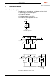
"UniVert 2" inverter Figure 2 illustrates the principle of an INV. In normal operation, the load is supplied "Online" by the INV. With systems comprising several parallel INVs, the load current is divided in accordance with the number of INVs. Depending on the system design, a power supply using up to 8 INVs can be realised. In addition to the parallel operation of several INVs, the reliability of supply can be further increased by integrating a static bypass switch, SBS.
"UniVert 2" inverter 2.5 Description of the SBS Its electronic high-performance components make the SBS highly overload-resistant and thus capable of quickly eliminating load short circuits. The SBS can be used as the central SBS for parallel operation of up to 8 INVs. Another outstanding characteristic of the SBS is its communication capability with other systems via integrated interfaces. The control electronics of the SBS have been designed on the basis of state-of-the-art microcontroller technology.
"UniVert 2" inverter 2.6 Principle of Operation of the SBS, Electrical If the SBS is supplied by connecting the mains or the load voltage, the corresponding operating status is automatically activated after 3 to 5 seconds. With mains operation, the DOU displays load voltage and SBS current. With all other operating statuses, in addition to the load voltage the corresponding status (ready, blocked, fault) is displayed. The toggle switch on the DOU serves exclusively to acknowledge SBS faults.
"UniVert 2" inverter 3 Function of the Inverter For technical data or unit settings, refer to the Technical Data Sheet in chapter 8. 3.1 DC Input The inverter is operated with 48 V (or 60 V) DC voltage. The input voltage is fuse-protected outside the INV. For details, refer to the technical data. An integrated softstart device limits the making current of the inverter to a value smaller than the rated input current. The input voltage is continuously monitored. (See chapter 3.3.) 3.
"UniVert 2" inverter 3.7 ON/OFF Switch The inverter is set ready for operation using the DOU switch on the front panel. The monitoring functions with their respective messages are only active when the inverter is switched on. After switch-off, all faults are acknowledged. The settings of the DIL switches are only accepted if the unit is switched off! 3.
"UniVert 2" inverter Switches S2.4, S2.5 and S2.6: Own Address (INV) The settings must be different on all INVs! Standard setting: Address 1: S2.4, S2.5 and S2.6 open S2.4 S2.5 S2.
"UniVert 2" inverter 3.
"UniVert 2" inverter 4 Function of the SBS (optional) For the technical data or unit settings, refer to the chapter “Technical Data”. 4.1 Operating Statuses The following operating statuses are possible: "PowerUp": Status after PowerUp or Reset. The control system checks the ambient conditions. "on": Mains operation: The SBS supplies the load. "ready": In the event of load voltage deviation or INV failure / switch-off, the SBS takes over the load without interruption, i.e.
"UniVert 2" inverter 4.3 AC Mains Input (X1) The SBS is connected to a 230 V AC mains. The input voltage is fuse protected outside the SBS. For details refer to the technical data. The input voltage is continuously monitored (see chapter 4.4). When the mains voltage is present, the green "mains present" LED lights up. 4.4 AC Busbar (X2) The AC busbar is either supplied by the INV output voltage or the SBS output voltage which corresponds to the SBS circuit voltage.
"UniVert 2" inverter 4.10 CAN Bus Interfaces (X6, X7) The unit can be controlled and monitored via the 10-pin CAN bus connector X6, if the SBS is installed in a power supply cabinet with PSM control unit. The CAN bus connector X7 is always required for communication with the INV when operated with SBS. In this case, only the end of the bus on the INV must have a terminating resistor connected; a bus terminating resistor is integrated in the SBS! (See Figure 1.) 4.
"UniVert 2" inverter Switches S3.7 and S3.8: number of redundant INVs S3.7 S3.8 0 INVs 0 0 1 INV 0 1 2 INVs 1 0 3 INVs 1 1 The settings must be the same on all INVs and the SBS! Standard setting: S3.7 and S3.8 open Switches S3.4 and S3.5: not used Switch S3.6: Switchover with gap (yes/no) Standard setting: switchover not with gap - S3.6 open i.e. in the event of phase deviations between INV and SBS, the SBS blocks. If switchover with gap is selected (- S3.
"UniVert 2" inverter With SBS ready: "U=230.0V" Load voltage " ready" Operating status With SBS blocked: "U=230.0V" Load voltage "blocked" Operating status With SBS Power Up: " " (nothing displayed) "PowerUp" Operating status With SBS fault: " " (nothing displayed) " fault" Operating status The busbar voltage and current values are displayed with three decimals before and one decimal after the decimal point. The display accuracy corresponds to class 1 with respect to the rated output value of the unit.
"UniVert 2" inverter Switchover with gap: The switchover from INV to SBS is carried out without interruption if the INV and SBS circuit are synchronous. If the INV and SBS circuit are not synchronous, the SBS does not block in this operating mode. If the INV is switched off due to asynchronism or if it fails, the load is supplied by the SBS after a load voltage gap of 140 ms.
"UniVert 2" inverter 5 Start-Up 5.1 Installation When installing the INV, the following regulations must be observed: • The INV has been designed for use in a dry room, practically free of dust. • It is imperative to observe the specifications concerning ambient temperature and site altitude (see chapter “Technical Data”). • Severe dust accumulation or a chemically aggressive atmosphere are not permissible; the system must be especially protected against conductive, humid dust deposits and condensation.
"UniVert 2" inverter Parallel INV operation: • Switch off the INV, switch on miniature circuit-breaker F1 • Set the DIL switches • Insert the AC fuses • Connect the DC supply • Switch on all INVs one after the other • (The output contactors K7 of the INVs start at the same time as soon as n-R INV have been switched on) • Connect the load i 5.
"UniVert 2" inverter 6 Maintenance Attention! Disconnect the unit from the power supply prior to all maintenance work. Always observe the safety instructions! (See chapter 1.) The INV consists of state-of-the-art components which are almost non-wearing. We do, however, recommend regular visual and functional tests of the unit to maintain its continuous availability and operational reliability.
"UniVert 2" inverter 7 Troubleshooting Attention! All work on the unit may be carried out by specially trained qualified personnel only. Always observe the safety instructions! (See chapter 1.) 7.
"UniVert 2" inverter 8 Technical Data 8.1 General Data INV DC input current ............................ < rated input current DC fuse required ........................... gL 80 A with type 3.3 kVA 48 V gL 63 A with type 3.3 kVA 60 V gL 20 A with type 3.3 kVA 220 V gL 80 A with type 1.5 kVA 24 V gL 36 A with type 1.5 kVA 48 V gL 32 A with type 1.5 kVA 60 V gL 25 A with type 2.5 kVA 110 V Manufacturing and type test .......... In acc. with DIN 60146 Part 1-1 Emitted interference in acc.
"UniVert 2" inverter Messages ...................................... - Operation LED green - Output voltage ok LED green - Input undervoltage UE< LED red - Input overvoltage UE> LED red - Fault LED red - Overtemperature ϑ> LED red - Collective fault LED red Remote signals (X3) ...................... Operation and collective fault message via potential-free relay contact (safe isolation). Max. contact load: 150 V DC < 1.6 A Min. contact load: 12 V 0.1 A Monitoring systems........................
"UniVert 2" inverter Mechanical stability and vibration resistance................. To VDE 0160 Version 5.88 Item 7.2.2 Surface painted with ...................... RAL 7032 (front panel) Dimensions (w x h x d) .................. 483 x 174 x 460 mm (19" x 4 height modules) (type 1.5 and 3.3 kVA) 483 x 174 x 400 mm (19" x 4 height modules) (type 2.5 kVA) Weight ........................................... Approx. 46.5 kg (type 3.3 kVA) Approx. 39 kg (type 2.5 kVA) Approx. 33.1 kg (type 1.
"UniVert 2" inverter - Power cables ............................... Burst test in acc. with EN 61000-4-4, 2 kV Surge test in acc. with EN 61000-4-5, 2 kV asymmetrical - Control cables ............................. Burst test in acc. with EN 61000-4-4, 2 kV Surge test in acc. with EN 61000-4-5, 2 kV asymmetrical Functional extra-low voltage .......... With safe isolation at UO ≤ 60 V DC to VDE 0100 Part 410 11.83 Section 4.3.2 Overload behaviour ....................... 1.6 x rated current for 1 minute 1.
"UniVert 2" inverter Protection class ............................. IP 20 Cooling .......................................... Forced air cooling Intake air temperature ................... At rated current 0°C to 45°C, measured below the SBS Storage temperature...................... -20°C to +70°C Ambient conditions ........................ IEC 721 Part 3-3 Class 3K3 / 3Z1 / 3B1 / 3C2 / 3S2 / 3M3 Site altitude....................................
"UniVert 2" inverter 8.3 Electrical Data Type E-number G48 – 60 E230/14,4/2rfg-CFp3,3 3000000352 Rated output capacity 3.3 kVA with power factor 0.8 Power factor range Rated output voltage 0 inductive to 0 capacitive 230 V ±0.5 static, ±3% dynamic at 100% load connection 50 Hz ±0.05% Output frequency THD factor Rated output current DC rated input voltage DC rated current Efficiency G220 E 230/14,4/2rfg-CFp3,3 300000601 < 3% 14.4 A 14.
"UniVert 2" inverter Type E-number G48 – 60 E230/6,5/2rfg-CFp1,5 3000000351 Rated output capacity 1.5 kVA with power factor 0.8 Power factor range Rated output voltage 0 inductive to 0 capacitive 230 V ±0.5 static, ±3% dynamic at 100% load change 50 Hz ±0.05% Output frequency THD factor Rated output current DC rated input voltage DC rated current Efficiency G24 E230/6,5/2rfg-CFp1,5 3000000602 < 3% 6.5 A 6.
"UniVert 2" inverter Type G110 E230/10,9/2rfg-CFp2,5 3000000263 E-number Rated output capacity 2.5 kVA with power factor 0.8 Power factor range Rated output voltage 0 inductive to 0 capacitive 230 V ±0.5 static, ±3% dynamic at 100% load change 50 Hz ±0.05% Output frequency THD factor < 3% Rated output current 10.9 A DC rated input voltage 110 V -15% ... +20% DC rated current 20.
"UniVert 2" inverter Type E230 E230/115/2-VFp26,5-8 3000000646 E-number Rated output capacity 26.
"UniVert 2" inverter 9 Dimensional Drawing Figure 6 Inverter dimensions (type 1.5 and 3.
"UniVert 2" inverter Figure 7 Inverter dimensions (type 2.
"UniVert 2" inverter Front view 483 460 11.5 101.6 X12 177 (4 height mod.) UniVert 2 X1, X2 PE connection 7 X7 37.