WSP 1510 S Deutsch Wärmespeicher mit statischer Entladung Gebrauchs- und Montageanweisung WSP 1510 S English Storage Heater with Static Discharge Operating and Installation instructions WSP 1510 S Français Accumulateur à décharge statique Notice d’utilisation et de montage WSP 1510 S Nederlands Warmteaccumulator met statische ontlading Gebruiks- en montagehandleiding 00 Titel WSP_1510S.p65 1 27.01.
Deutsch English 2 Table of Contents 1. Gebrauchsanweisung Für den Benutzer 1.1 Gerätebeschreibung ________________ 1.2 Bedienung _______________________ 1.3 Sicherheitshinweise ________________ 1.4 Pflege und Wartung ________________ 1.5 Wichtiger Hinweis _________________ Was tun wenn . . . ? ________________ 6 6 7 7 8 8 1. Operating instructions For the user 1.1 Technical description ______________ 1.2 Operation _______________________ 1.3 Safety instructions ________________ 1.
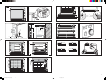
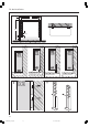
4 c d (5) (5) 4 (4) a 5 (4) b 5 6 14 13 60 5 14 6 3 464 A1 7 8 15 16 1 15 8 9 3 2 1 e 3 2 1 d 3 2 1 c 3 2 1 b 3 2 1 a 3 2 1 11 1 AEG 3 10 f 17 18 9 12 4 01 Ausklappseite WSP_1510S.p65 3 2 2 5 2 17.06.
Für den Benutzer 1. Gebrauchsanweisung 1.1 Gerätebeschreibung Mit dem Wärmespeicher wird während der preisgünstigen Freigabezeiten von Niedertarifstrom (abhängig vom Energie-Versorgungs-Unternehmen, überwiegend während der Nachtstunden) elektrisch erzeugte Wärme gespeichert und über die Oberfläche des Gerätes wieder abgegeben. 1.2 Bedienung Die Bedienung des Gerätes erfolgt am Bedienfeld (1) an der rechten Seitenwand (Abb. 1). 1.2.1 Wärmespeicherung Über den Wählknopf (Abb.
Für den Benutzer Deutsch 1.3 Sicherheitshinweise Das Gerät darf nicht – in Räumen betrieben werden, die durch Chemikalien, Staub, Gase oder Dämpfe feuer- oder explosionsgefährdet sind; – in unmittelbarer Nähe von Leitungen oder Behältnissen betrieben werden, die brennbare oder explosionsgefährdete Stoffe führen oder enthalten; – betrieben werden, wenn die Mindestabstände zu angrenzenden Objektflächen unterschritten werden.
Für den Benutzer und den Installateur 1.5 Wichtiger Hinweis Diese Anweisung sorgfältig aufbewahren, bei Besitzerwechsel dem Nachfolger aushändigen. Bei etwaigen Instandsetzungsarbeiten dem Fachmann zur Einsicht überlassen. Was tun wenn . . . ? • der Wärmespeicher nicht warm wird für den Benutzer für den Fachmann Prüfen Sie, ob . . . . . . der Wählknopf auf Stellung 3 eingestellt ist. . . . in Ihrem Sicherungskasten die zugehörigen Sicherungen defekt sind oder der FI-Schalter abgeschaltet hat.
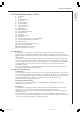
Für den Installateur Deutsch 2. Montageanweisung 2.1 Technische Daten 197 741 Entladung 21 Ladung 546 85 165 89 89 563 70 83 Ø 9mm Aufstellung und elektrischer Anschluss müssen von einem Fachmann unter Beachtung dieser Montageanweisung durchgeführt werden. Gewicht mit Steinen Anschluss Leistung Bemessungsaufladung max. Aufladung PH Speichersteine Anzahl Pakete (Steine) Steingewicht kW kWh kWh WSP 1510 S 106 1/N/PE ~ 50 Hz 230 V 1,5 12 16,2 Stck. kg 9 (18) 76 kg 9 02 DE WSP_1510S.
Für den Installateur 741 498,5 80,5 546 50 (6 x) 166 Entladung Entladung Entladung Ladung Ladung Entladung a a Ladung Ladung a a b Montage bei nicht tragfähigen Wänden Bodenaufstellung a Entladung Ladung Montage bei nicht ausreichend tragfähigen Wänden b 10 02 DE WSP_1510S.p65 10 27.01.
Für den Installateur 1 2 3 4 5 6 7 8 9 10 11 12 13 14 15 17 18 19 A1 V4 X16 X17 Deutsch 2.2 Gerätebeschreibung (Seite 3, Abb.
Für den Installateur Anschluss an DC-Steuersignal (X3) (siehe Stromlaufplan Seite 18) Ist in der Anlage eine Aufladesteuerung mit DC-Steuersignal (Gleichspannung 0,91 V -„ 1,43 V) installiert, „muss das Steuersignal an die werkseitig abgedeckten Steuerklemmen „DC + (Plus-Pol) und „DC - (Minus-Pol)„ angeklemmt„ werden (Polarität beachten!). An die Klemmen „DC + und „DC - darf nicht das 230 V AC-Steuersignal angeschlossen werden. Der Aufladeregler würde sonst zerstört.
Für den Installateur Deutsch 2.3 Vorschriften und Bestimmungen • Auf Beipack in der Geräteverpackung achten! • Die Bau- und Garagenverordnung des Landes ist zu berücksichtigen. • Die Aufstellfläche muss eine ausreichende Tragfähigkeit haben. Im Zweifelsfall ist ein Bausachverständiger zu Rate zu ziehen (Gewichte der Wärmespeicher siehe „Technische Daten“). • Mindestabstände zu angrenzenden Objektflächen sind einzuhalten (Abb. 2 und 2a).
Für den Installateur 2.4.2 Bodenfreie Gerätebefestigung mit Wandkonsolen Vor der Geräteaufstellung sind zwei Wandhalterungen (19) unter Berücksichtigung der Sicherheitsabstände an die Befestigungswand anzuschrauben (Maße siehe Technische Daten" " Seite 9). Bei dieser Montageart ist folgendes zu beachten: Ist eine tragfähige Wand vorhanden, kann das Gerät über die beiliegenden Wandhalterungen an der Aufstellwand befestigt werden.
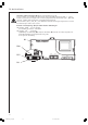
Für den Installateur Deutsch Anschluss Die elektrischen Anschlussleitungen bei Bedarf zugentlasten und gemäß dem elektrischen Schaltplan im Gerät (auf der Innenseite der rechten Seitenwand) oder dem nebenstehenden Anschlussplan anschließen.
Für den Installateur Anschlussplan Anschlussplan. . .. . . bei Ansteuerung . .. ...
Für den Installateur Deutsch 2.6 Erstinbetriebnahme Kurzschlussgefahr Laderegler Bei Spannungsmessung an den Thermorelaiskontakten wird bei Masseschluss – Abrutschen der Messspitzen – der Aufladeregler zerstört. Die Anzeige leuchtet weiterhin Grün"! " 2.6.1 Aufladung Das Gerät kann ohne Erstaufheizung in Betrieb genommen werden. Die Aufladung erfolgt entweder von Hand über den Einsteller des elektronischen Aufladereglers oder automatisch über die vorhandene Elfamatic-Aufladesteuerung.
Für den Installateur Stromlaufplan WSP 1510 S A1: B1: E1 - E6: F1: F2: K1: N4: R1: V4: X1: X2: X3: X16: X17: Elektronischer Aufladeregler Kerntemperaturfühler-Aufladung Heizkörper (Speicher) Sicherheits-Temperaturbegrenzer Sicherung (250 V 2A träge) Thermorelais Temperaturbegrenzer - Aufladung Einsteller - Aufladung (Wählknopf) Kontrollleuchte Betrieb Notbetrieb Netzanschlussklemme Anschlussklemme DC-Anschlussklemme 0,91 - 1,43 V Steuersignalanpassung 4-stufig Leistungsreduzierer 4-stufig elektron.
Für den Installateur Deutsch Achtung! Bei 3/PE AC 50Hz 230V Netz Umverdrahtung des Lastkreises des Wärmespeichers erforderlich! Stromlaufplan für 3/PE AC 50Hz 230V Umverdrahtung des Lastkreises des Wärmespeichers erforderlich! xxx Litze vi von E2 abziehen und auf E6 stecken! xx Litze br von E6 abziehen und auf E4 stecken! x Litze ws von E4 abziehen und auf E2 stecken! E1 - E6:Heizkörper (Speicher) F1: Schutz-Temperaturbegrenzer N1: Temperaturbegrenzer - Aufladung N4: Temperaturbegrenzer - Auflad
Kundendienst und Garantie 3. Kundendienst und Garantie AEG-Geräte werden mit Sorgfalt konstruiert und gebaut. Erst nach einer Reihe von Prüfungen verlassen sie unser Werk. Sollte trotzdem eine Störung auftreten, nehmen Sie bitte mit der Ihnen am nächstgelegenen AEG-Kundendienststelle Kontakt auf oder rufen Sie uns unter der Service-Telefonnummer an. Bitte halten Sie dabei die E-Nr. und F-Nr. des Gerätes bereit. Sie finden die Nummern auf dem Typenschild.
Kundendienst und Garantie Deutsch Die Kosten Für die Dauer der Garantie übernehmen wir sämtliche Materialkosten sowie alle im Zusammenhang mit der Fehlerbehebung entstandenen Kosten. Die Haftung Für das Abhandenkommen oder die Beschädigung eines Gerätes durch Diebstahl, Feuer, Aufruhr oder ähnliche Ursachen können wir keine Haftung übernehmen.
For the User 1. Operating Instructions 1.1 Technical Description Storage heaters store electrically generated heat during low-cost electricity tariff periods (depending on the electricity supply company, mainly during the night hours) and discharge it through the surface of the unit. 1.2 Operation The unit is operated by the control panel (1) on the right side wall (fig. 1). 1.2.1 Heat Storage The degree of heat storage (charging) is determined by the selector knob (fig. 16).
For the User 1.3 Safety Instructions English The unit must not – be operated in rooms where there is a risk of fire or explosion due to chemicals, dust, gases or fumes; – be operated in the immediate vicinity of pipes or containers which carry or contain inflammable or explosive substances; – be operated when the minimum distances from adjacent object surfaces are not kept.
For the User and the Fitter 1.5 Important Note Keep these instructions in a safe place, pass on to the new owner in case of a change of ownership. Make them available to the specialist in the case of repair work. What to do when . . . ? • the storage heater does not get hot For the User For the specialist Check whether . . . . . . the selector knob is set to position 3. . . . the corresponding fuses in your fuse box are defective or the FI switch has switched off. Eliminate the cause! Check whether . .
For the Fitter 2. Installation Instructions 2.1 Technical Data 197 741 Entladung 21 Ladung 546 85 89 English 165 89 563 70 83 Ø 9mm The unit must be installed and connected by a specialist under consideration of these installation instructions. Weight with blocks kg Connection Power kW Reference charging kWh kWh max. charging PH Storage blocks Number of packages (blocks) pcs. Block weight kg WSP 1510 S 106 1/N/PE ~ 50 Hz 230 V 1.5 12 16.2 9 (18) 76 25 03 GB WSP_1510S.p65 25 27.01.
For the Fitter 741 498,5 80,5 546 50 (6 x) 166 Entladung Entladung Entladung Ladung Ladung Entladung a a Ladung Ladung a a b Montage beion nicht Mounting tragfähigen Wänden unstable walls Floor installation Bodenaufstellung a Entladung Ladung Montage bei nicht ausreichend Mounting on walls of limited stability tragfähigen Wänden b 26 03 GB WSP_1510S.p65 26 27.01.
For the Fitter 2.2 Technical Description (page 3, fig.
For the Fitter Connection to DC control signal (X3) (see circuit diagram page 18) If a charging control unit with DC control signal (DC voltage 0.91 V-1,43 V) is installed in the system, the control signal must be connected to the control terminals covered at the factory ”DC +” (plus pole) and ”DC-” (minus pole) (Pay attention to polarity!). The 230 V AC control signal may not be connected to the ”DC +” and ”DC –” terminals. The charging control unit would otherwise be destroyed.
For the Fitter 2.3 Rules and Regulations English • Pay attention to the packing slip! • The national building and garage regulations must be taken into account. • The installation area must have a sufficient floor load capacity. In case of doubt a building surveyor should be consulted (for weights of the storage heaters, see ”Technical Data”). • The minimum distance from adjacent object surfaces must be kept (figs. 2 and 2a).
For the Fitter 2.4.2 Fastening of the Units with Floor Clearance with Wall Consoles Before installing the unit, two wall holders (19) must be screwed to the wall under consideration of the safety distances (dimensions see ”Technical data” page 9). The following must be observed with this installation site: If a stable wall is available, the unit can be fixed to the installation wall with the wall holders provided.
For the Fitter Connection Relieve the strain on the electrical connecting leads as required and connect according to the electrical circuit diagram in the device (on the inside of the right side wall) or the connection diagram opposite. If the angle plate in the switching area for holding the mains terminals is poorly accessible due to too small a spacing, it can be swung forward during connection work after loosening the screw (not removing) in the rear wall.
For the Fitter Anschlussplan ... Connection diagram ... bei Ansteuerung ohne Heizungsschütz . .. ...
For the Fitter 2.6 First-time Operation Short-circuit danger charging control unit When measuring the voltage at the thermal relay contacts the charging control unit is destroyed in the case of ground connection – slipping of the measuring peaks. The display still lights ”green”! 2.6.1 Charging The unit can be started without initial heating. Charging takes place either manually with the adjuster of the electronic charging control unit or automatically with the available Elfamatic charging control unit.
For the Fitter Circuit diagram WSP 1510 S A1: B1: E1 - E6: F1: F2: K1: N4: R1: V4: X1: X2: X3: X16: X17: Electronic charging control unit Core temperature sensor - charging Heating element (storage heater) Safety temperature limiter Fuse (250 V / 2 A slow-blow) Thermal relay Temperature limiter - charging Adjuster – charging (selector knob) Pilot lamp operation emergency operation Mains terminal Terminal DC terminal 0.91 – 1.43 V Control signal adapter 4-stage Output reducer 4-stage electron.
For the Fitter Caution! On a 3/PE AC 50 Hz 230 V mains Rewiring of the storage heater load circuit necessary! Circuit diagram for 3/PE AC 50Hz 230 V Rewiring necessary in the storage heater! xxx pull off vi wire from E2 and plug to E6 English xx pull off br wire from E6 and plug to E4 x pull off ws wire from E4 and plug to E2 E1 - E6:(storage) heater F1: protective temperature limiter N1: temperature limiter - charging N4: temperature limiter - charging X1: mains terminal Jumpers must be wire
Environment and recycling 3. Environment and recycling Please help us to protect the environment by disposing of the packaging in accordance with the national regulations for waste processing. Guarantee For guarantee please refer to the respective terms and conditions of supply for your country. The installation, electrical connection and first operation of this appliance should be carried out by a qualified installer.
A l’intention de l’utilisateur 1. Notice d’utilisation 1.1 Description de l’appareil Les accumulateurs thermiques permettent d’emmagasiner la chaleur produite par le courant électrique au cours des plages horaires à tarif réduit (en fonction de l’opérateur énergétique, la plupart du temps pendant la nuit). 1.2 Commande L’appareil est commandé à partir du panneau de commande (1) situé sur la paroi latérale droite (ill. 1). Français 1.2.
A l’intention de l’utilisateur 1.3 Consignes de sécurité L’appareil ne doit pas – être exposé à la poussière, aux produits chimiques, aux gaz ou aux vapeurs présentant un risque d’incendie ou d’explosion ; – se trouver à proximité immédiate de conduites ou de récipients contenant des produits inflammables ou explosifs ; – être utilisé à une distance inférieure aux distances minimales imposées par rapport aux objets proches.
A l’intention de l’utilisateur et de l’installateur 1.5 Remarque importante Conserver avec soin cette notice d’utilisation et de montage pour pouvoir la remettre, le cas échéant, au nouveau propriétaire. La mettre à disposition du spécialiste chargé d’effectuer l’entretien de l’appareil. Que faire si … ? • l’accumulateur ne se réchauffe pas A l’intention de l’utilisateur à l’intention du spécialiste Vérifier si . . . . . . le sélecteur est en position 3. . . .
A l’intention de l’installateur 2. Notice de montage 2.1 Caractéristiques techniques 197 741 Entladung 21 Ladung 546 85 165 89 89 563 70 83 Ø 9mm L’installation et le raccordement électrique doivent être effectués par un spécialiste conformément aux présentes instructions de montage. Poids (avec les pierres) kg Raccordement Puissance kW Charge de mesure kWh kWh Charge maxi.
A l’intention de l’installateur 741 498,5 80,5 546 50 (6 x) 166 Entladung Entladung Entladung Ladung Ladung Entladung a a Ladung Ladung a a b a Entladung Ladung Montage nicht ausreichend Mursbei à force portante limitée tragfähigen Wänden Murs à force Montage bei ausreichend tragfähigen Wänden portante suffisante Français Montage bei nicht Murs à force tragfähigen Wänden portante nulle Montage au sol Bodenaufstellung b 41 04 FR WSP_1510S.p65 41 27.01.
A l’intention de l’installateur 2.2 Description de l’appareil (page 3, ill.
A l’intention de l’installateur Raccordement au signal de commande CC (X3) (voir schéma électrique page 18) Si l’installation est équipée d’une gestion de la charge à signal de commande CC (courant continu 0,91 V – 1,43 V), le signal de commande doit être branché sur les bornes de commande « CC + » (pôle positif) et « CC –» (pôle négatif) (tenir compte de la polarité !) recouvertes à l’usine. Le signal de commande 230 V CA ne doit pas être branché aux bornes « CC + » et « CC –».
A l’intention de l’installateur 2.3 Consignes et réglementations • Tenir compte de tout ce qui se trouve dans l’emballage ! • Respecter la réglementation concernant les bâtiments et les garages du pays concerné. • La surface d’installation doit présenter une force portante suffisante. En cas de doute, faire appel à un expert en bâtiments (poids de l’accumulateur de chaleur voir « Caractéristiques techniques »). • Respecter les distances minimales par rapport aux objets proches (ill. 2 et 2a).
A l’intention de l’installateur 2.4.2 Fixation à l’aide de supports muraux Avant d’installer l’appareil, visser deux fixations murales (19) en tenant compte des écarts de sécurité au mur (pour les cotes se reporter aux « Caractéristiques techniques » page 9). Pour ce type de montage, tenir compte des points suivants : Si le mur présente une force portante suffisante, l’appareil peut être fixé au mur par les fixations jointes à la fourniture.
A l’intention de l’installateur Raccordement Libérer les câbles électriques d’une éventuelle traction et les brancher conformément au schéma des connexions électriques de l’appareil (sur la face interne de la paroi latérale droite) ou au schéma des raccordements qui se trouve à coté.
A l’intention de l’installateur Anschlussplan ... Schéma des raccordements ... Ansteuerung . .. ...
A l’intention de l’installateur 2.6 Première mise en service Danger de court-circuit Régulateur de charge Lors de la mesure de tension aux contacts du relais thermique, risque de destruction du régulateur de charge en cas de court-circuit à la masse (glissement des pointes d’essai). Le témoin reste sur « vert » ! 2.6.1 Charge L’appareil peut être mis en service sans préchauffage.
A l’intention de l’installateur Schéma électrique WSP 1510 S A1: B1: E1 - E6: F1: F2: K1: N4: R1: V4: X1: X2: X3: X16: X17: Régulateur électronique de charge Température interne - Charge Eléments chauffants (accumulateur) Limiteur de température Fusible (250 V 2A à action retardée) Relais thermique Limiteur de température - Charge Régulateur – Charge (sélecteur) Témoin de fonctionnement en mode secours Bornier secteur Bornier Bornes CC 0,91 – 1,43 V Adaptation du signal de commande en 4 étapes Réducteur d
A l’intention de l’installateur Attention ! Sur le 3/PE AC 50 Hz 230 V secteur Il est nécessaire de modifier le câblage d'origine de l'accumulateur de chaleur ! Schéma électrique du 3/PE AC 50 Hz 230 V Il est nécessaire de modifier le câblage d'origine comme ci-dessous ! xxx Débrancher le fil vi (violet) de E2 et le brancher sur E6 xx Débrancher le fil br (brun) de E6 et le brancher sur E4 x Débrancher le fil ws (blanc) de E4 et le brancher sur E2 E1 - E6:éléments chauffants (accumulateur) F1: limit
Environnement et recyclage 3. Environnement et recyclage Nous vous demandons de nous aider à préserver l'environnement. Pour ce faire, merci de vous débarrasser de l'emballage conformément aux règles nationales relatives au traitement des déchets. Français Garantie La garantie est à faire valoir dans le pays où l'appareil a été acheté. A cette fin, veuillez prendre contact avec la filiale AEG Home Comfort concernée, à défaut l'importateur agréé.
Voor de gebruiker 1. Gebruiksaanwijzing 1.1 Omschrijving van het apparaat Met warmteaccumulatoren wordt tijdens de laag tarief periode afhankelijk van het nutsbedrijf, meestal nachtstroom) elektrisch opgewekte warmte opgeslagen en via het oppervlak van het apparaat weer afgegeven. 1.2 Bediening De bediening van het apparaat gebeurt op het bedieningspaneel (1) op de rechter zijwand (afb. 1). 1.2.1 Warmteaccumulatie Met de keuzeschakelaar (afb. 16) wordt de accumulatiegraad (opladen) bepaald.
Voor de gebruiker 1.3 Veiligheidsvoorschriften Het apparaat mag niet – in ruimten worden gebruikt die brand- of explosiegevaarlijk zijn door de aanwezigheid van chemicaliën, stof, gassen of dampen; – in de onmiddellijke nabijheid van leidingen of reservoirs worden gebruikt, die brandbare of explosieve stoffen bevatten; – worden gebruikt wanneer de minimale afstand tot aangrenzende objecten niet in acht wordt genomen.
Voor de gebruiker en de installateur 1.5 Belangrijke aanwijzing Deze aanwijzing zorgvuldig bewaren, bij eventuele verkoop van het apparaat aan de nieuwe eigenaar overhandigen. Tijdens eventuele reparatiewerkzaamheden ter inzage aan de vakman geven. Wat te doen wanneer . . . ? • de warmteaccumulator niet warm wordt Voor de gebruiker Voor de vakman controleer of . . . . . . de keuzeschakelaar op stand 3 staat. . . .
Voor de installateur 2. Montagehandleiding 2.1 Technische specificaties 197 741 Entladung 21 Ladung 546 85 165 89 89 563 70 83 Ø 9mm Het plaatsen en de elektrische aansluiting moeten, met in acht neming van de montagehandleiding, door een vakman worden uitgevoerd. kg kW kWh kWh st. kg WSP 1510 S 106 1/N/PE ~ 50 Hz 230 V 1,5 12 16,2 9 (18) 76 Nederlands Gewicht met stenen Aansluiting Vermogen Berekend opladen max.
Voor de installateur 741 498,5 80,5 546 50 (6 x) 166 Entladung Entladung Entladung Ladung Ladung Entladung a a Ladung Ladung a a b Montage beiwanden nicht Montage bij tragfähigen Wänden zonder draagkracht Vloeropstelling Bodenaufstellung a Entladung Ladung Montagebei bij nicht wanden zonder Montage ausreichend voldoende draagkracht tragfähigen Wänden b 56 05 NL WSP_1510S.p65 56 27.01.
Voor de installateur 2.2 Beschrijving van het apparaat (pagina 3, afb.
Voor de installateur Aansluiting op DC-besturingssignaal (X3) (zie schakelschema pagina 18) Wanneer in de installatie een oplaadbesturing met DC-besturingssignaal (gelijkspanning 0,91 V - 1,43 V) is geïnstalleerd, moet het besturingssignaal op af fabriek afgedekte besturingsklemmen „DC +„ (pluspool) en „DC -„ (minpool) worden geklemd (let op de polariteit!). Op de klemmen „DC +„ en „DC -„ mag geen 230 V AC-besturingssignaal worden aangesloten. Anders wordt de oplaadregelaar onherstelbaar beschadigd.
Voor de installateur 2.3 Voorschriften en bepalingen • Let op de bijverpakte onderdelen in de verpakking van het apparaat! • De bouwvoorschriften van het desbetreffende land moeten in acht worden genomen. • De plaats waar het apparaat wordt geplaatst moet voldoende draagkracht hebben. In geval van twijfel moet een bouwdeskundige om advies worden gevraagd (Zie de „Technische gegevens" voor het gewicht van de accumulatoren). • De minimale afstand tot aangrenzende objecten moet worden aangehouden (afb.
Voor de installateur 2.4.2 Met wandbeugels los van de vloer bevestigen van de apparaten Voor de bevestiging van het apparaat moeten twee wandhouders (19), rekening houdend met de veiligheidsafstanden, aan de bevestigingswand (zie voor de maten “Technische gegevens” op pagina 9) worden geschroefd. Tijdens deze montagewijze het onderstaande in acht nemen: Wanneer een voldoende sterke wand beschikbaar is kan het apparaat met de meegeleverde wandhouders aan de wand worden bevestigd.
Voor de installateur Aansluiting Bij de elektrische aansluitleidingen eventueel zorgen voor een trekontlasting en overeenkomstig het schakelschema in het apparaat (op de binnenkant van de rechter zijwand) of het aansluitschema aansluiten.
Voor de installateur Anschlussplan ... . . . Aansluitschema Ansteuerung ohne Heizungsschütz . .....
Voor de installateur 2.6 Eerste inbedrijfstelling Kortsluitgevaar oplaadregelaar Wanneer de spanning op de thermorelaiscontacten wordt gemeten bij massasluiting – wegglijden van de meetvoelers – wordt de oplaadregelaar onherstelbaar beschadigd. Het controlelampje brandt dan weliswaar nog steeds “groen”! 2.6.1 Opladen Het apparaat kan direct in gebruik worden genomen.
Voor de installateur Schakelschema WSP 1510 S A1: B1: E1 - E6: F1: F2: K1: N4: R1: V4: X1: X2: X3: X16: X17: Elektronische oplaadregelaar Kerntemperatuur - opladen Verwarmingselement (accumulator) Veiligheidstemperatuurbegrenzer zekering (250V 2A traag) Thermorelais Temperatuurbegrenzer - opladen Regelaar – opladen (keuzeschakelaar) Controlelampje werking noodwerking Netaansluitklemmen Aansluitklemmen DC-aansluitklem 0,91 - 1,43 V Besturingsignaalaanpassing 4-traps Vermogensreductievoorziening 4-traps El
Voor de installateur Attentie! Bij 3/PE AC 50 Hz 230 V netvoeding Het is noodzakelijk dat de originele bedrading van de accumulator wordt omgezet! Elektrisch schema voor 3/PE AC 50 Hz 230 V Het is noodzakelijk dat de originele bedrading wordt omgezet! xxx Draad vi van E2 lostrekken en op E6 aansluiten xx Draad br van E6 lostrekken en op E4 aansluiten x Draad ws van E4 lostrekken en op E2 aansluiten E1 - E6:Verwarmingselement Veiligheidstemperatuurbegrenzer N1: Temperatuurbegrenzer - verwarming N4:
Milieu en recycling 3. Milieu en recycling Wij verzoeken u ons bij de bescherming van het milieu behulpzaam te zijn. Verwijder de verpakking daarom overeenkomstig de voor de afvalverwerking geldende nationale voorschriften. Garantie Aanspraak op garantie bestaat uitsluitend in het land waar het toestel gekocht is. U dient zich te wenden tot de vestiging van AEG Home Comfort of de importeur hiervan in het betreffende land.
Adressen und Kontakte Vertriebszentrale Regionen EHT Haustechnik GmbH Markenvertrieb AEG Gutenstetter Straße 10 90449 Nürnberg info@eht-haustechnik.de www.aeg-haustechnik.de Tel. 0 18 03 / 91 13 23 Fax 09 11 / 96 56 - 44 4 AEG Kundendienst Kundendienstzentrale Holzminden Fürstenberger Str. 77 37603 Holzminden Briefanschrift 37601 Holzminden Der Kundendienst und Ersatzteilverkauf ist in der Zeit von Montag bis Donnerstag von 7.15 bis 18.00 Uhr und Freitag von 7.15 bis 17.
GERMANY www.aeg-haustechnik.de info@eht-haustechnik.