WSP 2010, WSP 3010, WSP 4010, WSP 5010, WSP 6010, WSP 7010 Deutsch Wärmespeicher Standard-Baureihe Gebrauchs- und Montageanweisung WSP 2010, WSP 3010, WSP 4010, WSP 5010, WSP 6010, WSP 7010 English Electric Storage Heaters Standard Series Operating and Installation instructions WSP 2010, WSP 3010, WSP 4010, WSP 5010, WSP 6010, WSP 7010 Français Accumulateurs de chaleur Série standard Notice d’utilisation et de montage WSP 2010, WSP 3010, WSP 4010, WSP 5010, WSP 6010, WSP 7010 Warmteaccumulator stan
Deutsch English 2 Table of Contents 1. Gebrauchsanweisung Für den Benutzer 1.1 Gerätebeschreibung ________________ 1.2 Bedienung _______________________ 1.3 Sicherheitshinweise ________________ 1.4 Pflege und Wartung ________________ 1.5 Wichtiger Hinweis _________________ Was tun wenn . . . ? ________________ 6 6 7 7 8 8 1. Operating instructions For the user 1.1 Technical description ______________ 1.2 Operation _______________________ 1.3 Safety instructions ________________ 1.
c d a 18 16 b 5 6 14 13 60 4 5 15 6 4 464 7 (5) (5) (4) 8 5 (4) 15 16 1 17 9 9 3 2 1 e 3 2 1 d 3 2 1 c 3 2 1 b 3 2 1 a 3 2 1 1 3 10 f 3 2 2 3 17 18 10 AEG 11 12 19 4 01 Ausklappseite WSP_2010.p65 5 2 17.06.
Für den Benutzer 1. Gebrauchsanweisung 1.1 Gerätebeschreibung Mit Wärmespeichern wird während der preisgünstigen Freigabezeiten von Niedertarifstrom (abhängig vom Energie-Versorgungs-Unternehmen, überwiegend während der Nachtstunden) elektrisch erzeugte Wärme gespeichert. Diese wird entsprechend der gewünschten Raumtemperatur als Warmluft über ein Gebläse, zu einem geringen Anteil auch über die Geräteoberfläche, wieder abgegeben. 1.
Für den Benutzer Deutsch 1.3 Sicherheitshinweise Das Gerät darf nicht – in Räumen betrieben werden, die durch Chemikalien, Staub, Gase oder Dämpfe feuer- oder explosionsgefährdet sind; – in unmittelbarer Nähe von Leitungen oder Behältnissen betrieben werden, die brennbare oder explosionsgefährdete Stoffe führen oder enthalten; – betrieben werden, wenn die Mindestabstände zu angrenzenden Objektflächen unterschritten werden.
Für den Benutzer und Installateur 1.5 Wichtiger Hinweis Diese Anweisung sorgfältig aufbewahren, bei Besitzerwechsel dem Nachfolger aushändigen. Bei etwaigen Instandsetzungsarbeiten dem Fachmann zur Einsicht überlassen. Was tun wenn . . . ? • der Wärmespeicher nicht warm wird für den Benutzer für den Fachmann Prüfen Sie, ob . . . . . . der Wählknopf auf Stellung 3 eingestellt ist. . . . in Ihrem Sicherungskasten die zugehörigen Sicherungen defekt sind oder der FI-Schalter abgeschaltet hat.
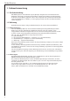
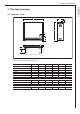
Für den Installateur Deutsch 2. Montageanweisung 2.1 Technische Daten B 245 Entladung 30 Ladung 650 85 165 95 95 X 80 130 Ø 9mm Aufstellung und elektrischer Anschluss müssen von einem Fachmann unter Beachtung dieser Montageanweisung durchgeführt werden. Breite „B" mm Gewicht (mit Steinen) kg Abstand „X" mm Anschluss Leistung kW Bemessungsaufladung kWh kWh max. Aufladung PH Speichersteine Anzahl Pakete (Steine) Stck.
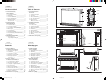
Für den Installateur 2.2 Gerätebeschreibung (Seite 3, Abb. 1) 1 2 3 4 5 6 7 8 9 10 11 12 13 14 15 16 17 18 19 20 21 Bedienfeld Deckel Seitenwand rechts Vorderwand Luftaustrittgitter Lufteintrittgitter Flusensieb Innere Vorderwand Speichersteine Abdeckblech Wärmedämmung Boden-Wärmedämmung Mischluftklappe Luftkanal Kabeldurchführung Luftführungsbaugruppe Heizkörper Gebläse Schutz-Temperaturregler - Entladung (N5) Schutz-Temperaturregler - Aufladung (N4) Sicherheitstemperaturbegrenzer (F1) 2.2.
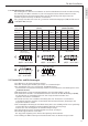
Für den Installateur Leistungsvarianten kW Anschlussvarianten Modell WSP 2010 WSP 3010 WSP 4010 WSP 5010 WSP 6010 WSP 7010 ➀ 100 % 8h-Heizkörper (Serie) ➃ ➁ ➂ 91,6 % 83,3 % 75 % 2,0 3,0 4,0 5,0 6,0 7,0 1,83 2,75 3,66 4,58 5,50 6,42 1,67 2,50 3,33 4,16 5,00 5,83 100 % PNenn 1 3 2 1 L3 L2 L1 X1 2 2,7 4,1 5,5 6,5 8,1 9,0 2,0 – – – – – 2,47 3,75 5,04 5,96 7,42 8,24 75 % PNenn 2,25 3,42 4,58 5,42 6,75 7,5 2,03 3,07 4,13 4,88 6,08 6,75 83,3 % PNenn 3 2 1 L3 L2 L1 X1 3/N/PE ~ 50 Hz 400 V 3/N/PE
Für den Installateur 2.4 Montageort Das Gerät darf nicht – in Räumen betrieben werden, die durch Chemikalien, Staub, Gase oder Dämpfe feuer- oder explosionsgefährdet sind; – in unmittelbarer Nähe von Leitungen oder Behältnissen betrieben werden, die brennbare oder explosionsgefährdete Stoffe führen oder enthalten; – betrieben werden, wenn die Mindestabstände zu angrenzenden Objektflächen unterschritten werden. In Räumen, in denen Abgase, Öl- und Benzingeruch usw.
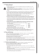
Für den Installateur Deutsch 2.5.1 Geräteaufstellung (Abb. 3–6) • Lufteintrittsgitter (6) an beiden Seiten leicht nach unten drücken, oben nach vorne kippen und abnehmen. Am Luftaustrittsgitter (5) beide Schrauben oben losschrauben und Gitter abnehmen (Abb. 3). • Vorderwand (4) mit 2 Schrauben unten lösen (innere Gewindelöcher), Vorderwand unten leicht anheben und abnehmen (Abb. 4, Abb. 5). Innere Vorderwand mit 2 Schrauben unten lösen leicht anheben und abnehmen.
Für den Installateur Für den Betrieb „Eindrahtsteuerung” ** ist eine Brücke zwischen „N” und „A2/Z2” zu legen! Leistungsanpassung entsprechend Nennaufladedauer Durch Umlegen bzw. Entfernen von Brücken an den Anschlussklemmen kann die Anschlussleistung an die vom EVU vorgegebene Nennaufladedauer angepasst werden.
Für den Installateur Deutsch Anschlussplan ... Anschlussplan ... . . . bei integrierten Raumtemperaturreglern RTI-E3/RTI-EP2 . . .
Für den Installateur 2.6 Erstinbetriebnahme 2.6.1 Funktionsprüfung Die Funktion des Gebläses für den Speicherteil durch Einschalten des Raumtemperaturreglers prüfen. 2.6.2 Aufladung Die Geräte können nach erfolgter Funktionsprüfung ohne Erstaufheizung in Betrieb genommen werden. Die Aufladung erfolgt entweder von Hand über den Einsteller des mechanischen Aufladereglers oder automatisch über die vorhandene Elfamatic-Aufladesteuerung.
Deutsch Für den Installateur Stromlaufplan WSP 2010 - 7010 E1 - E6: E7: F1: M1 - M3: N1: N5: N4: X1: X2: Integr.
Für den Installateur Achtung! Bei 3/PE AC 50Hz 230V Netz Umverdrahtung des Lastkreises des Wärmespeichers erforderlich! Stromlaufplan für 3/PE AC 50Hz 230V Umverdrahtung des Lastkreises des Wärmespeichers erforderlich! xxx Litze vi von E2 abziehen und auf E6 stecken! xx Litze br von E6 abziehen und auf E4 stecken! x Litze ws von E4 abziehen und auf E2 stecken! E1 - E6:Heizkörper (Speicher) F1: Schutz-Temperaturbegrenzer N1: Temperaturbegrenzer - Aufladung N4: Temperaturbegrenzer - Aufladung X1:
Kundendienst und Garantie Deutsch 3. Kundendienst und Garantie AEG-Geräte werden mit Sorgfalt konstruiert und gebaut. Erst nach einer Reihe von Prüfungen verlassen sie unser Werk. Sollte trotzdem eine Störung auftreten, nehmen Sie bitte mit der Ihnen am nächstgelegenen AEG-Kundendienststelle Kontakt auf oder rufen Sie uns unter der Service-Telefonnummer an. Bitte halten Sie dabei die E-Nr. und F-Nr. des Gerätes bereit. Sie finden die Nummern auf dem Typenschild.
Kundendienst und Garantie Die Kosten Für die Dauer der Garantie übernehmen wir sämtliche Materialkosten sowie alle im Zusammenhang mit der Fehlerbehebung entstandenen Kosten. Die Haftung Für das Abhandenkommen oder die Beschädigung eines Gerätes durch Diebstahl, Feuer, Aufruhr oder ähnliche Ursachen können wir keine Haftung übernehmen.
For the User 1. Operating Instructions 1.1 Technical Description Storage heaters store electrically generated heat during low-cost electricity tariff periods (depending on the electricity supply company, mainly during the night hours). This is then discharged according to the desired room temperature as hot air by a fan and to a small extent through the surface of the heater. 1.2 Operation The unit is operated by the control panel (1) on the right side wall (fig. 1). 1.2.
For the User 1.3 Safety Instructions The unit must not – be operated in rooms where there is a risk of fire or explosion due to chemicals, dust, gases or fumes; – be operated in the immediate vicinity of pipes or containers which carry or contain inflammable or explosive substances; – be operated when the minimum distances from adjacent object surfaces are not kept.
For the User and Fitter 1.5 Important Note Keep these instructions in a safe place, pass on to the new owner in case of a change of ownership. Make them available to the specialist in the case of repair work. What to do when . . . ? For the specialist Check whether . . . . . . the selector knob is set to position 3. . . . the corresponding fuses in your fuse box are defective or the FI switch has switched off. Eliminate the cause! Check whether . . . . . .
For the Fitter 2. Installation Instructions 2.1 Technical Data B 245 Entladung 30 Ladung 650 85 165 95 95 X 80 130 Ø 9mm The unit must be installed and connected by a specialist under consideration of these installation instructions. WSP 2010 605 Width ”B” mm 118 Weight (with storage blocks) kg 415 Distance ”X” mm Connection * 2.0 Power kW 16.0 Reference charging kWh 17.0 kWh max. charging PH Storage blocks 6 (12) Number of packages (blocks) pcs. 85 Block weight kg 3.
For the Fitter 2.2 Technical Description (page 3, fig. 1) Control panel Cover Right side wall Front wall Air outlet grille Air inlet grille Fluff screen Inside front wall Storage blocks Cover plate Thermal insulation Floor thermal insulation Mixing air flap Air duct Cable duct Air guidance assembly Heating element Fan Safety temperature regulator - discharging (N5) Safety temperature regulator - charging (N4) Safety temperature limiter (F1) English 1 2 3 4 5 6 7 8 9 10 11 12 13 14 15 16 17 18 19 20 21 2.
For the Fitter 2.2.2 Reducing the Output By moving or removing bridges at the terminals, the connection rating, factory wired to 100 % can be reduced by three levels (see the table). The dimensioning of the line cross sections and the fusing should correspond to the maximum possible output of the unit. A single-phase connection may be made according to the "Technical connection conditions" of the energy supply company only up to 2 kW (WSP 2010).
For the Fitter 2.4 Installation Site The unit may not – be operated in rooms where there is a risk of fire or explosion due to chemicals, dust, gases or fumes; – be operated in the immediate vicinity of pipes or containers which carry or contain inflammable or explosive substances; – be operated when the minimum distances from adjacent object surfaces are not kept. In rooms in which exhaust fumes, oil and petrol smells occur, the unpleasant smell may linger and could possibly cause soiling.
For the Fitter 2.5.1 Unit Installation (fig. 3-6) • Press the air inlet grille (6) down slightly on both sides, tip forward at the front and remove. Unscrew both screws at the air outlet grille (5) and remove the grille (fig. 3). • Loosen the front wall (4) with 2 screws at the bottom (inside threaded holes), lift the front wall slightly and remove (fig. 4). Loosen the inside front wall with 2 screws at the bottom and remove (fig. 5).
For the Fitter A bridged must be inserted between ”N” and ”A2/Z2” for operation with ”single-wire control”**! Power adaptation according to rated charging time By moving or removing bridges at the terminals, the output can be adapted to the rated charging time specified by the electricity supply company. 8h ➀ 8h (series) 9h ➁ 10h ➂ 2.0 3.0 4.0 5.0 6.0 7.0 1.83 2.75 3.66 4.58 5.5 6.42 1.67 2.5 3.33 4.16 5.0 5.
For the Fitter ConnectionAnschlussplan diagram . . . . . . . . . bei integrierten Raumtemperaturreglern . . .
For the Fitter 2.6 First-time Operation 2.6.1 Function Test Check the function of the fan for the storage unit by switching on the room temperature regulator. 2.6.2 Charging The units can be started without initial heating up after the function test. Charging takes place either manually with the adjuster of the mechanical charging control unit or automatically with the available Elfamatic charging control unit.
For the Fitter Circuit diagram WSP 2010 - 7010 E1 - E6: E7: F1: M1 - M3: N1: N5: N4: X1: X2: Integr.
For the Fitter Caution! On a 3/PE AC 50 Hz 230 V mains Rewiring of the storage heater load circuit necessary! Circuit diagram for 3/PE AC 50Hz 230 V Rewiring necessary in the storage heater! xxx pull off vi wire from E2 and plug to E6 English xx pull off br wire from E6 and plug to E4 x pull off ws wire from E4 and plug to E2 E1 - E6:(storage) heater F1: protective temperature limiter N1: temperature limiter - charging N4: temperature limiter - charging X1: mains terminal Jumpers must be wire
Environment and recycling 3. Environment and recycling Please help us to protect the environment by disposing of the packaging in accordance with the national regulations for waste processing. Guarantee For guarantee please refer to the respective terms and conditions of supply for your country. The installation, electrical connection and first operation of this appliance should be carried out by a qualified installer.
A l’intention de l’utilisateur 1. Notice d’utilisation 1.1 Description de l’appareil Les accumulateurs de chaleur permettent l’accumulation de chaleur produite par le courant électrique au cours des plages horaires à tarif réduit (en fonction du fournisseur, la plupart du temps pendant la nuit). Cette chaleur est ensuite restituée sous forme d’air chaud par le biais d’un ventilateur ou, dans une moindre mesure, par la surface de l’appareil en fonction de la température souhaitée. 1.
A l’intention de l’utilisateur 1.3 Consignes de sécurité L’appareil ne doit pas – être exposé à la poussière, aux produits chimiques, aux gaz ou aux vapeurs présentant un risque d’incendie ou d’explosion ; – se trouver à proximité immédiate de conduites ou de récipients contenant des produits inflammables ou explosifs ; – être utilisé à une distance inférieure aux distances minimales imposées par rapport aux objets proches.
A l’intention de l’utilisateur et de l’installateur 1.5 Remarque importante Conservez avec soin ce mode d’emploi pour pouvoir le remettre, le cas échéant, au nouveau propriétaire. Le mettre à disposition du spécialiste chargé d’effectuer l’entretien de l’appareil. Que faire si … ? • l’accumulateur ne se réchauffe pas A l’intention de l’utilisateur à l’intention du spécialiste Vérifier si . . . . . . le sélecteur est en position 3. . . .
A l’intention de l’installateur 2. Notice de montage 2.1 Caractéristiques techniques B 245 Entladung 30 Ladung 650 85 165 95 X 95 80 130 Ø 9mm L’installation et le raccordement électrique doivent être effectués par un spécialiste conformément aux présentes instructions de montage. WSP 2010 Largeur « l » mm 605 Poids (avec les pierres) kg 118 Distance « X » mm 415 Raccordement * Puissance kW 2,0 Charge de mesure kWh 16,0 kWh Charge maxi.
A l’intention de l’installateur 2.2 Description de l’appareil (page 3, ill.
A l’intention de l’installateur 2.2.2 Réduction de la puissance absorbée En déplaçant ou enlevant des cavaliers sur les bornes, il est possible de réduire de 3 niveaux (voir tableau) la puissance absorbée réglée départ-usine au niveau maximum.”La dimension des sections de câbles et les fusibles doivent être choisis en fonction de la puissance maximale possible de l’appareil.
A l’intention de l’installateur 2.4 Site de montage L’appareil ne doit pas – être exposé à la poussière, aux produits chimiques, aux gaz ou aux vapeurs présentant un risque d’incendie ou d’explosion ; – se trouver à proximité immédiate de conduites ou de récipients contenant des produits inflammables ou explosifs ; – être utilisé à une distance inférieure aux distances minimales imposées par rapport aux objets proches.
A l’intention de l’installateur 2.5.1 Installation de l’appareil (ill. 3-6) • Pousser légèrement la grille de sortie d’air (6) des deux côtés vers le bas, faire basculer sa partie supérieure vers le haut et la retirer ; Desserrer les deux vis du haut de la grille de sortie d’air (5) et retirer la grille (ill. 3). • Desserrer (trous internes) 2 vis du bas de la paroi avant (4), soulever légèrement la partie inférieure de la paroi avant et la retirer (ill. 4, ill. 5).
A l’intention de l’installateur En fonctionnement unifilaire**, poser un cavalier entre « N » et « A2/Z2 » ! Adapter la puissance en fonction de la durée nominale de charge La puissance de raccordement peut être adaptée à la durée nominale de charge de l’opérateur énergétique par décalage ou retrait de cavaliers aux bornes.
A l’intention de l’installateur Anschlussplan ... Schéma des raccordements . . . bei integrierten Raumtemperaturreglern RTI-E3/RTI-EP2 . . .
A l’intention de l’installateur 2.6 Première mise en service 2.6.1 Contrôle de fonctionnement Contrôler le fonctionnement de la soufflante de l’élément d’accumulation en mettant en marche le thermostat d’ambiance. 2.6.2 Charge Une fois le contrôle de fonctionnement achevé, les appareils peuvent être mis en service sans préchauffage. La charge s’effectue soit manuellement par le biais du régulateur de charge mécanique ou automatiquement avec la gestion de charge Elfamatic disponible.
A l’intention de l’installateur Schéma électrique WSP 2010 - 7010 E1 - E6: E7: F1: M1 - M3: N1: N5: N4: X1: X2: Elément chauffant (accumulateur) Résistance de chauffage Limiteur de température Soufflante Limiteur de température - Charge Limiteur de température – Tiroir du ventilateur Limiteur de température - Charge Bornier secteur Bornier Signal de gestion de charge 230 V CA 1 L3 L2 L1 N L3 L2 L1 3/N/PE ~ 50 Hz 400 V 46 Chauffage auxiliaire E8: N2: N3: S1: Elément chauffant Thermostat – Chauffage a
A l’intention de l’installateur Attention ! Sur le 3/PE AC 50 Hz 230 V secteur Il est nécessaire de modifier le câblage d'origine de l'accumulateur de chaleur ! Schéma électrique du 3/PE AC 50 Hz 230 V Il est nécessaire de modifier le câblage d'origine comme ci-dessous ! xxx Débrancher le fil vi (violet) de E2 et le brancher sur E6 xx Débrancher le fil br (brun) de E6 et le brancher sur E4 Français x Débrancher le fil ws (blanc) de E4 et le brancher sur E2 E1 - E6:éléments chauffants (accumulateur)
Environnement et recyclage 3. Environnement et recyclage Nous vous demandons de nous aider à préserver l'environnement. Pour ce faire, merci de vous débarrasser de l'emballage conformément aux règles nationales relatives au traitement des déchets. Garantie La garantie est à faire valoir dans le pays où l'appareil a été acheté. A cette fin, veuillez prendre contact avec la filiale AEG concernée, à défaut l'importateur agréé.
Voor de gebruiker 1. Gebruiksaanwijzing 1.1 Omschrijving van het apparaat Met warmteaccumulatoren wordt tijdens de laag tarief periode (afhankelijk van het nutsbedrijf, meestal nachtstroom) elektrisch opgewekte warmte opgeslagen. Deze wordt overeenkomstig de temperatuur in de ruimte via een ventilator als warme lucht, en voor een gering deel ook als uitstralingswarmte van het oppervlak van het apparaat, weer afgegeven. 1.
Voor de gebruiker 1.3 Veiligheidsvoorschriften Het apparaat mag niet – in ruimten worden gebruikt die brand- of explosiegevaarlijk zijn door de aanwezigheid van chemicaliën, stof, gassen of dampen; – in de onmiddellijke nabijheid van leidingen of reservoirs worden gebruikt, die brandbare of explosieve stoffen bevatten; – worden gebruikt wanneer de minimale afstand tot aangrenzende objecten niet in acht wordt genomen.
Voor de gebruiker en de installateur 1.5 Belangrijke aanwijzing Deze aanwijzing zorgvuldig bewaren, bij eventuele verkoop van het apparaat aan de nieuwe eigenaar overhandigen. Tijdens eventuele reparatiewerkzaamheden ter inzage aan de vakman geven. Wat te doen wanneer . . . ? • de warmteaccumulator niet warm wordt Voor de gebruiker Voor de vakman controleer of . . . . . . de keuzeschakelaar op stand 3 staat. . . .
Voor de installateur 2. Montagehandleiding 2.1 Technische specificaties B 245 Entladung 30 Ladung 650 85 165 95 X 95 80 130 Ø 9mm Het plaatsen en de elektrische aansluiting moeten, met in acht neming van de montagehandleiding, door een vakman worden uitgevoerd. WSP 2010 605 Breedte „B" mm 118 Gewicht (met stenen) kg 415 Afstand „X" mm Aansluiting * 2,0 Vermogen kW 16,0 Berekend opladen kWh 17,0 kWh max. opladen PH Accumulatiestenen 6 (12) Aantal pakken (stenen) st.
Voor de installateur 2.2 Beschrijving van het apparaat (pagina 3, afb.
Voor de installateur 2.2.2 Aansluitvermogen reduceren Door het omleggen c.q. verwijderen van bruggen op de aansluitklemmen kan het aansluitvermogen, dat af fabriek op 100 % is ingesteld, in combinatie met een oplaadgraadreductie op de oplaadregelaar 3 vermogenstrappen (zie pagina 12) worden gereduceerd. De afmetingen van de leidingdiameters en de beveiliging moeten overeenkomstig het maximaal mogelijke vermogen van het apparaat worden uitgevoerd.
Voor de installateur 2.4 Montageplaats Het apparaat mag niet – in ruimten worden gebruikt die brand- of explosiegevaarlijk zijn door de aanwezigheid van chemicaliën, stof, gassen of dampen; – in de onmiddellijke nabijheid van leidingen of reservoirs worden gebruikt, die brandbare of explosieve stoffen bevatten; – worden gebruikt wanneer de minimale afstand tot aangrenzende objecten niet in acht wordt genomen. In ruimten waarin uitlaatgassen, olie- en benzine, vluchtige stoffen enz.
Voor de installateur 2.5.1 Plaatsing van het apparaat (afb. 3-6) • Het luchttoevoerrooster (6) aan beide kanten lichtjes naar beneden drukken, aan de bovenkant naar voren tuimelen en verwijderen; Op het luchtafvoerrooster (5) beide schroeven aan de bovenkant losdraaien en het rooster verwijderen (afb. 3). • De voorwand (4) met 2 schroeven aan de onderkant losdraaien (inwendige schroefdraadgaten), de voorwand aan de onderkant lichtjes optillen en verwijderen (afb. 4).
Voor de installateur Voor de werking met "enkeldraadsbesturing" ** moet een brug tussen "N" en "A2/Z2" worden gemaakt. Aanpassing van het vermogen overeenkomstig de nominale oplaadduur Door het omleggen c.q. verwijderen van bruggen op de aansluitklemmen kan het aansluitvermogen op de door de nutsbedrijf bepaalde nominale oplaadduur worden aangepast.
Voor de installateur Anschlussplan ... Aansluitschema ... . . . bei integrierten Raumtemperaturreglern . . .
Voor de installateur 2.6 Eerste inbedrijfstelling 2.6.1 Werkingscontrole De werking van de ventilator voor het accumulatordeel door het inschakelen van de thermostaat controleren. 2.6.2 Opladen De apparaten kunnen na een succesvolle werkingscontrole zonder eerste opwarming in gebruik worden genomen. Het opladen gebeurt hetzij met de hand met de instelling van de elektronische oplaadregelaar of automatisch met de beschikbare Elfamatic-oplaadbesturing.
Voor de installateur Schakelschema WSP 2010 - 7010 E1 - E6: E7: F1: M1 - M3: N1: N5: N4: X1: X2: Verwarmingselement (accumulator) Verwarmingsweerstand Veiligheidstemperatuurbegrenzer Ventilator Temperatuurbegrenzer - opladen Temperatuurbegrenzer - ventilatorenchuiflade Temperatuurbegrenzer - opladen Netaansluitklemmen Aansluitklemmen Geïntegr.
Voor de installateur Attentie! Bij 3/PE AC 50 Hz 230 V netvoeding Het is noodzakelijk dat de originele bedrading van de accumulator wordt omgezet! Elektrisch schema voor 3/PE AC 50 Hz 230 V Het is noodzakelijk dat de originele bedrading wordt omgezet! xxx Draad vi van E2 lostrekken en op E6 aansluiten xx Draad br van E6 lostrekken en op E4 aansluiten x Draad ws van E4 lostrekken en op E2 aansluiten E1 - E6:Verwarmingselement Veiligheidstemperatuurbegrenzer N1: Temperatuurbegrenzer - verwarming N4:
Milieu en recycling 3. Milieu en recycling Wij verzoeken u ons bij de bescherming van het milieu behulpzaam te zijn. Verwijder de verpakking daarom overeenkomstig de voor de afvalverwerking geldende nationale voorschriften. Garantie Aanspraak op garantie bestaat uitsluitend in het land waar het toestel gekocht is. U dient zich te wenden tot de vestiging van AEG of de importeur hiervan in het betreffende land.
Adressen und Kontakte Vertriebszentrale Regionen EHT Haustechnik GmbH Markenvertrieb AEG Gutenstetter Straße 10 90449 Nürnberg info@eht-haustechnik.de www.aeg-haustechnik.de Tel. 0 18 03 / 91 13 23 Fax 09 11 / 96 56 - 44 4 AEG Kundendienst Kundendienstzentrale Holzminden Fürstenberger Str. 77 37603 Holzminden Briefanschrift 37601 Holzminden Der Kundendienst und Ersatzteilverkauf ist in der Zeit von Montag bis Donnerstag von 7.15 bis 18.00 Uhr und Freitag von 7.15 bis 17.
GERMANY www.aeg-haustechnik.de info@eht-haustechnik.