
Operation Manual


30
L-
L-
L
L
SH
SH
LE
LE
LE
LE
L
L
L
L
N
N
N
N
A1
A1
A1
A1
Z1
Z1
Z1
Z1
A2
A2
A2
A2
Z2
Z2
Z2
Z2
DC
DC
AC
AC
(N)
(N)
(N)
(N)
(N)
(N)
(N)
Aufladesteuerung
230 V-System
Aufladesteuerung
230 V-System
“Eindraht-
steuerung”
Brücken (L) - (L-SH) und (N) - (N)
bei Ansteuerung Heizungsschütz
entfernen
ohne
Brücken (L) - (L-SH) und (N) - (N)
bei Ansteuerung Heizungsschütz
entfernen
ohne
1/N 230V
1/N 230V
Raumtempe-
raturregler
N/PE 400V
N/PE 400V
N/PE 400V
1/N/PE 230V
Aufladesteuerung A1/A2
Aufladesteuerung A1/A2
Aufladesteuerung
L1/L2/L3
(ggf. über Heizungsschütz)
L1/L2/L3
(ggf. über Ladeschütz)
L1/L2/L3
(ggf. über Ladeschütz)
RTA-S
(RTNZ-S
)
[mit Schalter f. Zusatzhzg.]
Aufladesteuerung
Kleinspannungs-System
Aufladesteuerung
Kleinspannungs-System
X3
X3
N
N
LE`
LE`
LH
LH
LH`
LH`
N
N
N
N
TA
TA
N
N
N
N
LE
LE
+
+
-
-
L3
L3
L3
L3
L2
L2
L2
L2
L1
L1
L1
L1
2
2
2
2
1
1
1
1
3
3
3
3
X1
X1
X1
X1
X2
X2
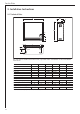
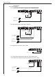
Anschlussplan . . .
. . . bei integrierten Raumtemperaturreglern RTI-E3/RTI-EP2
. . . bei wandmontierten Raumtemperaturreglern RTA-S/RTNZ-S
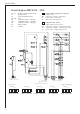
. . . bei Wärmespeicheraustausch “alt-neu” mit wandmontiertem
Raumtemperaturregler und fehlender Tagstrom-Versorgung
. . . bei einphasigen Anschluss (max. 2 kW)
à
à
à
à
à
à
àà
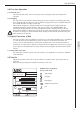
For the Fitter
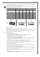
. . . for integrated room temperature regulators RTi 100 M/RTi 101 EP
. . . for wall-mounted room temperature regulators
. . . for single-phase connection (max. 2 kW)
. . . for storage heater replacement ”old-new” with wall-mounted
room temperature regulator and missing daytime electricity supply
Connection diagram . . .
*
Bridges (L) - (L-SH) and (N) - (N)
for control without
remove heater contactor
AC
charging-
control unit
230 V system
Charging control unit A1/A2
1/N ~ 50 Hz 230 V
L1/L2/L3
(poss. via heating contactor)
N/PE ~ 50 Hz 400 V
*
Bridges (L) - (L-SH) and (N) - (N)
for control without
remove heater contactor
AC
charging-
control unit
230 V system
Charging control unit A1/A2
1/N ~ 50 Hz 230 V
L1/L2/L3
(poss. via heating contactor)
N/PE ~ 50 Hz 400 V
wall-mounted room
temperature controllers
L1/L2/L3
(poss. via heating contactor)
N/PE ~ 50 Hz 400 V
Charging control unit
room temperature
regulator
**
”Single wire control”
1/N/PE ~ 50 Hz 230 V