AEGIS 1000 Installation Manual Part No.
Copyright © 2002 HAI All Rights Reserved Home Systems Plus www.aegishome.
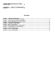
CONTENTS INTRODUCTION ............................................5 INSTALLATION..............................................5 CONTROLLER HOOKUP ............................................ 5 ABOUT SECURITY ZONES ......................................... 7 BURGLAR ZONE HOOKUPS ................................. 7 ABOUT FIRE ZONES.................................................... 9 TWO-WIRE SMOKE DETECTORS......................... 9 FOUR-WIRE SMOKE DETECTORS .......................
SMOKE DETECTOR INSTALLATION GUIDELINES................................................. 46 APPENDIX A – CONTACT ID REPORTING FORMAT........................................................ 47 FIGURES FIGURE 1 – CONTROLLER HOOKUP................................................................................................................................. 6 FIGURE 2 - OVERALL CONNECTIONS DIAGRAM ..........................................................................................................
INTRODUCTION This installation guide is intended as an aid to installing the Aegis 1000 automation system. The installer should also have thoroughly reviewed and understood the Aegis 1000 Owner's Manual, which has important information regarding final setup of the system. This manual assumes that the installer has a basic understanding of installing a security system. This guide applies to the Aegis 1000 controller.
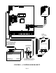
TWO - WAY 4 CONDUCTOR POWER LINE INTERFACE REVERE P/N RT-1640SL OR EQUIVALENT 1/4" SPACING THE BATTERY IS NON-POWER LIMITED. THE BATTERY LEADS MUST BE SEPERATED FROM ALL OTHER POWER LIMITED WIRING IN THE ENCLOSURE BY AT LEAST 1/4". COLD WATER PIPE OR GROUND ROD 14 GA. WIRE POWER TRANSFORMER BLACK WIRE TO RED WIRE TO + YUASA NP7-12 OR EQUIVALENT BATTERY 12V 7AH GOUNDING METHOD MUST BE IN ACCORDANCE WITH THE NATIONAL ELECTRIC CODE, ANSI/NFPA 70. FIGURE 1 – CONTROLLER HOOKUP Page 6 16.
ABOUT SECURITY ZONES Zones 1-8 on the controller and zones 9-24 on the expander may be configured as security zones, fire zones, temperature zones, or auxiliary inputs. Zones 7 and 8 on the controller and zones 9-16 may also be configured as a PESM. Zone 8, however, is the only input that can be used with 2-wire smoke detectors. An external 1000-ohm end-of-line zone resistor is required for all zones unless the Setup item ZONE RESISTORS is set to "No".
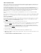
ZONE OUT2 SWITCH 12V (OUTPUT) J9 NRM (NO) WARNING (NC) TO PREVENT RISK FROM ELECTRIC SHOCK, DE-ENERGIZE THIS UNIT AND DISCONNECT TELEPHONE LINES BEFORE SERVICING. 1K EOL BURGLARY ZONE SMK SMK COM 12V 12V 4-WIRE SMOKE ZN J9 SWITCH 12V (OUTPUT) OUT2 ZN 1K EOL Z8 ZONE ZN 12V 2-WIRE SMOKE 1K EOL ZONE Z8 NRM 2-WIRE FIRE ZONE 4-WIRE FIRE ZONE NOTES: 1. ALL CIRCUITS EXCEPT FOR THE BATTERY ARE POWER-LIMITED (CLASS II) 2.
ABOUT FIRE ZONES The Aegis 1000 system supports normally open (closed for alarm), two-wire smoke detectors. Two wire smoke detectors can only be connected to Zone 8. Four wire smoke detectors can be connected to any zone (1 8). An external 1000-of line resistor must be -wire or four wire) or Gas zone, the Zone 8 Jumper (J9) must be Smoke dete end of line resistor is a 150 ohms. Use an End of End of line resistor: 1000 ohms. Maximum loop resistance Line Resistor Assembly in UL Listed Installations. 3.
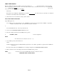
WHEN Z8 USED FOR SMOKE, J9 MUST BE IN THIS POSITION SYSTEM SENSOR MODEL 2100TS THIS OUTPUT MUST BE CONFIGURED AS A SWITCHED OUTPUT BOTTOM PLATE ZONE ZONE SYSTEM SENSOR MODEL 2100TS BOTTOM PLATE ZONE ZONE HAI MODEL 1503A0011 1K OHM EOL RESISTOR FIGURE TWO WIRE FIRE ZONE CONNECTIONS Page 10
GREEN BLACK YELLOW THIS OUTPUT MUST BE CONFIGURED AS A SWITCHED OUTPUT WHEN Z8 USED FOR SMOKE, J9 MUST BE IN THIS POSITION RED SYSTEM SENSOR MODEL 2112/24TR SYSTEM SENSOR MODEL 2112/24TR ZONE YELLOW ZONE YELLOW ZONE GREEN ZONE GREEN +12V RED +12V RED GND BLACK GND BLACK BOTTOM PLATE SYSTEM SENSOR MODEL 2112/24TR YELLOW ZONE YELLOW ZONE GREEN ZONE GREEN +12V RED +12V RED GND BLACK GND BLACK BLACK RED RED VIOLET GREEN VIOLET YELLOW EOL POWER SUPERVISION RELAY MO
TELEPHONE CONNECTIONS 1. If an RJ31X jack has been supplied by the telephone company, it is probably wired correctly and the controller can be connected by plugging the supplied 8 conductor telephone cable into the RJ31X jack. The other end of the cable is spaded (remove the spade connectors from the wires used). The green, red, brown, and gray wires must be connected to the controller at the designated terminals under the section of the board marked 'PHONE'. 2.
GRAY BROWN RED GREEN BEND TAB UP IF NECESSARY TO ENSURE TIGHT FIT RED(-) GREEN(+) TELEPHONE NETWORK INTERFACE CUSTOMER ACCESS RED(-) GREEN(+) SURGE ARRESTOR SURGE ARRESTOR MUST BE GROUNDED! RJ11 HOUSE PHONE JACK(S) TO ALL HOUSE TELEPHONES, KSU, AND COMPUTERS TO TELCO INTERFACE AT SURGE ARRESTOR FIGURE 5 - RJ31X JACK CONNECTIONS Page 13
LCD CONSOLE HOOKUP 1. 4 LCD Consoles (Models 11A00- -6, 7, and - Use 4 conductor 22be divided by the total number of consoles at the end of the run. For example, for 4 consoles, the maximum length reduces to The console should be m reach of young children. A good height is approximately 58 inches from the floor to the bottom of the console enclosure. 4. late (slots on bottom of console will release back plate, use a screwdriver). Mount the back plate to the wall.
LANGUAGE This option is to display the 'console setup' text on the LCD display in English, French, Italian, or Spanish. Select one of the languages, then press the # key. EXIT SETUP MODE To exit Setup Mode, press and hold the 4 and up arrow (ñ) keys simultaneously for about 1 second. The console will return to normal operation. You may need to press (*) to restore the display. CONSOLE SELF TEST Use the self test mode to verify the proper operation of the console. 1.
BOTTOM PLATE SUPPLIED CABLE FIGURE 6 - CONSOLE CONNECTIONS Page 16
BELL OUTPUT The Bell Output provides 12VDC to power bells, piezo sirens, self-contained sirens, and siren drivers (do not connect speakers to the Bell Output). Sounders can draw up to 1 amp MAXIMUM - (See Specifications for UL Ratings). 2. The Bell Output monitors the wiring to bells and sirens. It will report trouble if an open, short, or other wiring problem is detected in the supervised bell circuit. It will also make a digital dial out when violated. 3.
CONTROLLER OUTPUTS The Aegis 1000 provides 2 programmable hardwired voltage outputs on the controller and 8 voltage outputs on the Expansion Module.
REMOTE ARM/DISARM SWITCH 3. Configure one of the outputs as an "ARMED" and another output as an "OK TO ARM" output. These outputs are used to activate a red and a green LED based on the state of the alarm system. The "ARMED" and "OK TO ARM" outputs can supply a maximum of 100 mA each. These outputs are included in the total DEVICES load, which cannot exceed 500 mA. GREEN Configure one of the zone inputs as a KEYSWITCH zone.
AEGIS THERMOSTATS Aegis 1000 supports up to 2 Aegis Communicating Thermostats. The controller can send commands to the thermostat to change mode, cool setting, heat setting, status of fan and hold, and other items. Run a 3 (or 4) conductor wire from Aegis 1000 to the thermostat location. All thermostats are connected to the GRN (Green), BLK (Black), and YEL (Yellow) terminals in the section marked "TSTAT" on the Aegis 1000 controller. Connect the red COMM cable wire with the black COMM cable wire.
PROGRAMMABLE ENERGY SAVER MODULES Programmable Energy Saver Modules may be connected to: Controller: Expansion Module: Zone 7 and Output 1 Zone 1 and Output 1 and/or Zone 8 and Output 2 through Zone 8 and Output 8, respectively Note: Zones labeled 1-16 on the Expansion Module correspond to Zones 9-24. 1. The Aegis 1000 can support up to 10 Programmable Energy Saver Modules (2 on the controller and 8 on the expander). Each PESM requires one security zone input and one output.
4. Heat Pumps Programmable Energy Saver Modules are compatible with heat pumps, however, the savings gained by setting the heat pump back may be erased by the auxiliary heaters when the heat pump tries to recover from the setback. A PESM will work best with heat pumps that have one or more of the following features: a. An outdoor temperature switch that prevents the auxiliary heat from coming on unless it is very cold outside. This is sometimes called a "heat balance" switch. b.
RED BLACK YELLOW GREEN EXISTING LOW VOLTAGE THERMOSTAT PROGRAMMABLE ENERGY SAVER MODULE GREEN YELLOW RED BLACK RED LED ON - ENERGY SAVER IS OVERRIDING THERMOSTAT OFF - THERMOSTAT IS WORKING NORMALLY HEAT /AIR SYSTEM FIGURE 10 - PESM CONNECTIONS Page 23
BUILT-IN SERIAL INTERFACE Aegis 1000 has a serial interface built onto the controller (designated as J5 SERIAL). The interface is a modular connector located in the upper left corner of the controller. It uses the Aegis Link Protocol for connections to the Internet via Aegis WebLink, personal computers, and other optional interfaces like touchscreens, voice recognition, and home theater controls. The serial interface supports both RS-232 and RS-485 connections.
SYSTEM POWER UP PROCEDURE 1. Carefully review connections to the zones, grounds, sounders, and consoles. 2. Disconnect the sounders. 3. The positive lead to the battery should be disconnected. Make sure that the red battery wire is not touching anything. 4. Plug in the power transformer (transformer must be 16.5VAC, 40VA) - The AC ON LED should illuminate. - The STATUS LED should begin blinking at a rate of 1 blink per second. This indicates that the Aegis 1000 processor and software are working.
5. Record the owner's NAME and ADDRESS in the ADDRESS speech memory as shown in SETUP ADDRESS in the OWNER'S MANUAL (Press 8, 9, then 1111 or the current Master code to record the address). NOTE: DO NOT record any TOUCH TONES in the ADDRESS! 6. Check that all in-house phones are working. BURGLAR ZONE CHECK OUT 1. With all doors and windows closed and all motion detectors and security devices normal, you should have "SYSTEM OK" on the console. 2. If any zones are abnormal, check your wiring.
You should also: 4. Demonstrate arming and disarming. 5. Demonstrate home control. 6. Demonstrate setup and programming. 7. Deliver the Owner's Manual. 8. If the customer has subscribed to a central monitoring service, this should be explained. IN CASE OF TROUBLE CONSOLES If you experience trouble that seems to be with a console, try disconnecting the console and running the console self test as described under CONSOLE HOOKUPS in this manual.
8. Call HSP (800-401-4663) with the serial number for a return authorization number. Write the RA# on the outside of the package. 9. Return the controller to HSP at the address noted on the RA. Also include a brief description of the problem that you are having. 10. INSTALLATION: Follow the POWER UP and CHECK OUT procedures in this manual. FOR HELP: Call HSP, between the hours of 9:00 AM and 5:00 PM Eastern time, at (800) 401-4663. X-10 TROUBLESHOOTING TIPS 1.
DIGITAL COMMUNICATOR The Aegis 1000 digital communicator can use Contact ID, or Standard 4/2 or 3/1, (20 pps, 1800 Hz data, 2300 Hz handshake), or (10 pps, 1900 Hz data, 1400 Hz handshake), dual round compared format. Any central station with modern equipment can receive these formats. Compatible receivers are Ademco, Radionics, Osborne-Hoffman, Linear, FBI, and Silent Knight. It is up to the installer to verify compatibility.
3/1 FORMAT Older central stations may require a 3/1 format. To use 3/1 format, both account numbers must be changed to 3 digit codes and EVERY alarm code must be changed to a 1-digit code. Do not mix code lengths! OPENING AND CLOSING REPORTS The Aegis 1000 system can send opening and closing reports by user to the central station. When the system is disarmed by user code 1-8, the communicator can call the central station and report that the system was disarmed (opened) with the user code that was used.
INSTALLER SETUP This section describes the items that the installer must setup as part of system installation. The Installer Setup mode is used to configure the general operation of the system, the Outputs, the Zone Types, and the Digital Communicator. This information is covered only in this manual. All other SETUP items, including delay times, zone and unit names, voice dialer, and codes are covered in the Owner's Manual.
OUTPUT TYPE NUMBER GENERAL PURPOSE OK TO ARM ARMED PRE-ALM SNDR INT SNDR INT BURG SNDR INT FIRE SNDR EXT SNDR EXT BURG SNDR EXT FIRE SNDR BURG COMM FIRE COMM AUX COMM SWITCHED POWER DESCRIPTION 0 1 2 3 4 5 6 7 8 9 10 11 12 13 General Purpose Output OK To Arm Armed Pre-Alarm Sounder Interior Sounder Interior Burglary Sounder Interior Fire Sounder Exterior Sounder Exterior Burglary Sounder Exterior Fire Sounder Burglary Communicator Fire Communicator Auxiliary Communicator Switched Power Output For outp
The current Zone Type setting is shown on the bottom line. To change a zone type, use the arrow keys to scroll through the list of zone types then press ' # ' to select a new type. The display shows: SELECT TYPE: PERIMETER 1 × ZONE RESPONSE TIME All zones, in the Aegis 1000 are set to 300 milliseconds fixed response time.
There are two special types of ENTRY/EXIT ZONES for use with garage doors, or doors that are far away from the control console. They are called DOUBLE ENTRY DELAY and QUADRUPLE ENTRY DELAY zones. These zones have double or quadruple the ENTRY DELAY to give you additional time to reach the console to disarm the system upon returning. Only the ENTRY DELAY is extended on these zone types. The EXIT DELAY is not extended. If an ENTRY/EXIT ZONE is tripped first, all other zones will also be delayed.
FIRE EMERGENCY This zone type activates the fire alarm for a normally closed (open for alarm) and open collector (short to ground for alarm) switches. It is not supervised as required for UL Listed Installations and shall NOT be used in such installations. GAS This GAS ZONE will generate an alarm, activate the sounder (on - off - on - long off), and make a dial out. This zone type requires an external 1000-ohm end-of-line resistor.
TEMPERATURE The general-purpose TEMPERATURE ZONE type is typically used to monitor indoor temperatures and control devices. It sets the zone secure/not ready for program conditionals and event button activation. If FREEZE ALARM is enabled, it reports a potential freeze condition if the temperature falls below 40o. TEMPERATURE ALARM The TEMPERATURE ALARM ZONE type will generate an alarm (console beeper, no sirens) and dial out if the temperature goes above the high setpoint or drops below the low setpoint.
COMMUNICATOR TYPE This item is used to select the transmitting parameters of the digital communicator. The Aegis 1000 can transmit in FAST 2300 Hz (20 PPS) mode, in SLOW 1400 Hz (10 PPS) 3/1 format, and in Contact ID. COMMUNICATOR TYPE: 0=2300 1=1400 2=ID 2 × The default setting is 2 = ID (Contact ID). If you need to transmit to a 4/2 or 3/1 receiver, select the proper handshaking frequency (2300 Hz or 1400 Hz) and press ' # '.
To disable the digital communicator for a specific zone, set the alarm code to 0 or 00. The digital dialer will not report when this zone is tripped. ZONE 1 ALARM CODE: 0-FF 01 USER 8 CLOSE CODE: 0-FF 68 × THROUGH ↑ SETUP TEMPERATURES To configure temperatures from the Installer Setup Menu, press the 5 (Temp) key. TEMPERATURE DISPLAY This allows you to choose between Fahrenheit or Celsius temperature format.
NOTE: Remember this Installer code and do not disable. There is no way to reset or retrieve the code! If the code is forgotten or disabled, the Aegis 1000 controller must be sent back to the factory. Call for an RA#. ENABLE PC ACCESS This enables or disables the PC ACCESS feature. Factory default is enabled. ENABLE PC ACCESS: 0=NO 1=YES 1 × PC ACCESS CODE This code allows dealers to put an access code in the system that is separate from the customer's Master code and the Installer code.
To change the alarm reset time, enter a new time between 1-30 minutes, then press the ' # ' key. The default setting is 4 minutes. ARMING CONFIRMATION The Arming Confirmation is a quick pulse (squawk) given by the exterior siren when the alarm system is armed into a security mode and the EXIT DELAY is expired. ARMING CONFIRMATION: 0=NO 1=YES 0 × To enable the arming confirmation feature, press the 1 (YES) key, then press the ' # ' key. The default setting is disabled.
TIME DISPLAY This allows you to choose between AM/PM or 24 HOUR time format. TIME DISPLAY: 1=AM/PM 2=24HR 1 × DATE DISPLAY This allows you to choose between MONTH/DAY or DAY/MONTH date format. DATE DISPLAY: 1=MMDD 2=DDMM 1 × AC POWER FREQUENCY Set this to the appropriate AC Powerline Frequency. AC POWER FREQUENCY: 1=60HZ 2=50HZ 1 × DEAD LINE DETECT NOTE: To disable Aegis 1000 from detecting a dead line, set this item to '0'; otherwise adjust only under direction of HSP.
MODEL AND SOFTWARE VERSION The model number and software version for the system is displayed: AEGIS 1000 S/W VERSION 2.0 × RESET SYSTEM EEPROM Select the 1 (YES) key to reset the EEPROM. All programs, names, and setup items will be reset. All system RAM will also be initialized and the system will restart. This option, in effect, allows the system to be restored to factory fresh configuration.
MODULE 2 TYPE - MODULE 4 TYPE Module 2 is the module with the jumper set to 2, and so on. Set each module type from the list above. SERIAL 1 RATE Serial 1 Rate is the baud rate used for the built-in serial interface (J5 Serial) on the Aegis 1000 controller. Select the baud rate for the built-in serial interface from the list below. Use the arrow keys to select the baud rate then press #.
AEGIS 1000 SPECIFICATIONS Size: Controller: Console: Weight: 9.1 W x 12.1 H x 3.5 D 4.6 W x 4.5 H x 1.2 D Controller: Console: approx. 4.5 lb. approx. 0.5 lb. Operating Ranges: 32 - 122 degrees F (0 - 50 degrees C) 10 - 95 % relative humidity, non-condensing Power: 120 VAC, 60 Hz, 60 watts Transformer: 16.5 VAC, 40 VA, 50/60 Hz Battery: Sealed Rechargeable Lead–Acid, 12 volts Bell Fuse: Polyfuse: 1.35A Device Fuse: Polyfuse: .9 A Output Fuse: Polyfuse: .3 A Battery Fuse: Polyfuse: 2.
UNDERWRITER'S LABORATORIES (UL) INSTALLATION REQUIREMENTS The Aegis 1000 control unit (21A00-14) is suitable for Grade A household burglar and fire applications. Refer to UL1641 for installation requirements. 1. The line carrier (X-10) operation is considered supplementary. Operation of the line carrier devices was not investigated by UL. 2. For those zones programmed as PANIC, DURESS or POLICE EMERGENCY, the initiating device shall be a UL Listed Hold Up Device switch. 3.
SMOKE DETECTOR INSTALLATION GUIDELINES 1. Ceiling mounted smoke detectors should be located in the center of the room or hall, or not less than 4 inches from any wall. When the detector is mounted on a wall, the top of the detector should be 4 to 12 inches from the ceiling. 2. Do not install smoke detectors where normal ambient temperatures are above 100 deg. F (37.8 deg. C) or below 40 deg. F (4 deg. C).
APPENDIX A – CONTACT ID REPORTING FORMAT ZONE TYPE TRIP TROUBLE Entry/exit (also Double & Quad) Perimeter (also Latching) Night Interior (also Latching) Away Interior (also Latching) Panic Police Emergency Silent Duress Tamper (also Latching) Fire Fire Emergency Gas Auxiliary Emergency Trouble Freeze Water Auxiliary Fire tamper Temperature Alarm 134 131 132 132 120 120 122 137 110 110 151 150 330 159 154 none 321 152 370 370 370 370 375 375 375 370 373 373 373 370 330 370 370 none 321 370 EVENT CODE
800-401-HOME (4663) www.Aegishome.