
Installation Manual


3
Read and understand these instructions BEFORE attempting to install this product.
Failure to follow installation instructions and not using the provided hardware may
damage the intake tube, throttle body and engine.
1. Preparing Vehicle
a. Make sure vehicle is parked on level surface.
b. Set parking brake.
c. If engine has run in the past two hours, let it cool down.
d. Disconnect negative battery terminal.
e. Do not discard stock components after removal of the factory system.
2. Removal of stock system
a. Disconnect breather hose and any vacuum lines (if they are present) from the air inlet tube.
b.
CAUTION: Ensure the engine is completely cool before removing the coolant hose, or hot coolant
will escape from the cooling system and cause injury or damage. Be sure to capture any lost
coolant in a clean container.
Disconnect the water bypass hose from throttle body or the fast idle thermo valve, if equipped; located
at the lower portion of the throttle body. Disconnect the opposite side of the water bypass hose, which runs
to either the intake manifold or the water outlet neck. Remove the entire water bypass hose and breather
hose assembly from the vehicle. Disconnect the intake air bypass control valve hose where applicable.
c. Loosen and remove the air inlet tube from the throttle body.
d. Loosen and remove the stock air box from the vehicle.
NOTE: It is not necessary to remove the stock resonator from inside the fender well.
3. Installation of AEM
®
intake system.
a. When installing the intake system, do not completely tighten the hose clamps or mounting hardware until
instructed to do so.
b. Some applications use an inlet air temperature (IAT) sensor. If your application uses this sensor, then one
of the rubber grommets that are included in the kit must be installed in the pipe. Install the ½” I.D. rubber
grommet into the corresponding hole. Be sure that it is fully seated so as to prevent an air leak.
c. Install one black connector hose on the throttle body end of the inlet pipe. That is the end closer to the
breather nipple, or the end that is closest to the hole for the IAT sensor.
d. Install two hose clamps on the connector hose and just snug them down on the hose.
e. Slide the throttle body end of the inlet pipe onto the throttle body.
f. Gently tighten the hose clamps so that the pipe can still be rotated.
g.
NOTE: If your application does not have a support tab then skip to step 3h.
Some applications have a support tab that is welded onto the inlet pipe.
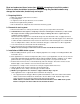
i. The support tab on the inlet pipe will line up with a threaded hole on the inner fender well. Install the
rubber isolator mount and attach the air inlet tube onto the rubber mount. Install the large fender
washer and the lock nut onto the isolator mount stud and snug it down.
NOTE: Failure to install the rubber mount will void all warranties of the AEM
®
intake system.
Below is a diagram of how the rubber mount should be installed.