
Manual

Page 5
INSTALL AEMnet ADAPTER HARNESS
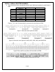
4. Table 2 below lists the corresponding CAN1L and CAN1H pin locations for each Series 2
EMS.
CAN1L (Green wire) CAN1H (White wire)
EMS
Adapter p/n
LOCATION LOCATION
30-6030
30-3430
C22 C21
30-6050
30-3432
D14 D10
30-6051
30-3432
D14 D10
30-6052
30-3432
D14 D10
30-6053
30-3432
D14 D10
30-6060
30-3432
C28 C29
30-6310
30-3431
77 87
30-6311
30-3431
57/77 67/87
30-6320
30-3435
33 13
Table 2: CAN1L and CAN1H pin locations
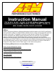
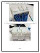
Figures 7, 8, 9, and 10 below show the connectors for each Series 2 EMS.
Figure 7: Wire-side view of pinout for 6030
Figure 8: Wire-side view of pinout for 6050, 6051, 6052, 6053, and 6060 EMS
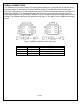
Figure 9: Wire-side view of pinout for 6310 and 6311 EMS
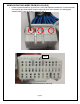
Figure 10: Wire-side view of Pinout for 6320 EMS