Infinity-6/8h Mini Harness User Manual 30-3705 THIS PRODUCT IS LEGAL IN CALIFORNIA FOR RACING VEHICLES ONLY AND SHOULD NEVER BE USED ON PUBLIC HIGHWAYS. AEM Performance Electronics AEM Performance Electronics, 2205 126th Street Unit A, Hawthorne, CA 90250 Phone: (310) 484-2322 Fax: (310) 484-0152 http://www.aemelectronics.
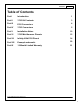
Contents I Table of Contents Part I Introduction 1 Part II 3705 Kit Contents 3 Part III ECU Connectors 4 Part IV 3705 Connectors 5 Part V Installation Notes 10 Part VI 3705 Mini-Harness Pinouts 12 Part VII Infinity-6/8h ECU Pinout 14 Part VIII Example schematic 20 Part IX 12 Month Limited Warranty 21 © 2014 AEM Performance Electronics I
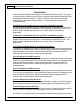
1 AEM Infinity Harness Manuals Introduction 1 Several universal wiring harness options are available for Infinity products. They range in complexity from simple plug and pin kits to complete engine harness assemblies that include power distribution centers. Custom wiring harness projects should only be undertaken by experienced harness builders. If in doubt, please contact AEM for recommendations.
2 but it can be used as a reference for any custom harness build based on the Infinity ECU. Please read the entire User Manual prior to beginning any installation.
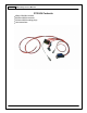
3 AEM Infinity Harness Manuals 3705 Kit 2Contents Infinity-6/8h Mini-Harness 80 Molex MX64 terminals 30 Molex MX64 sealing plugs User Instructions © 2014 AEM Performance Electronics
4 ECU Connectors 3 The Infinity-6/8h/8/10 ECUs use the MX123 Sealed Connection System from Molex. AEM strongly recommends that users become familiar with the proper tools and procedures before attempting any modifications or additions to these connector housings. The entire Molex user manual can be downloaded direct from Molex at http:// www.molex.com/mx_upload/family//MX123UserManual.
5 AEM Infinity Harness Manuals 3705 Connectors 4 Flash enable connector Not usually needed. Used under certain conditions to force the ECU into flash programming mode.
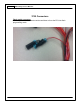
6 UEGO connector Connect to 30-3600 UEGO extension harness.
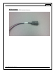
7 AEM Infinity Harness Manuals AEMNet connector Connect to optional AEMNet enabled devices.
8 EFI Main Relay Required for normal power sequencing function.
9 AEM Infinity Harness Manuals Flying lead bundle Wires are ink stamped with descriptions as follows: BATT GND BATT PWR Sensor GND SWT PWR 5V REF ACC PWR INJ PWR IGN PWR Connect directly to battery negative Connect directly to battery positive Connect to low reference (GND) of 5V analog sensors Ignition switch input.
10 Installation 5 Notes Wiring Conventions and EMI Some wire harness assemblies come pre-wired with all connectors, fuses, and relays needed to operate an engine. Harnesses that include a PDC generally require extension/termination of the flying leads to their appropriate devices, and additional sensors and other devices can be wired into the harness as needed for the specific application. The following guidelines should be adhered to while completing the required wiring.
11 AEM Infinity Harness Manuals It is recommended that the ECU be placed in an environment that does not expose it to temperatures above 85° Celsius (160F). In cases where the Infinity is to be used in place of the stock ECU, the location that the stock ECU occupied is suitable. On applications where the ECU is to be located in a different position than stock, the interior of the vehicle is best.
12 3705 Mini-Harness 6 Pinouts 20 Plug 40 Plug 60 Plug 80 Plug 19 Plug 39 Plug 59 Plug 79 Plug 18 Plug 38 Plug 58 Plug 78 Plug 17 Plug 37 Plug 57 Plug 77 Plug 16 Plug 36 Plug 56 Plug 76 Plug 15 Plug 55 Plug 75 Plug 54 Plug 74 Plug 53 Plug 73 Plug 12 Plug 35 WHT (Cable) CAN A + 34 GRN (Cable) CAN A 33 BLK GND 32 Plug 52 Plug 11 Plug 31 Plug 51 Plug 72 RED Harness Flash Enable 71 Plug 10 RED/BLK Battery perm power 9 ORG UEGO1 VM 8 BLK UEGO1 UN 7 PNK UEGO1 IP 6 GRN UEGO1 IA 5
13 AEM Infinity Harness Manuals Pins 10, 43, 48, 63 are absolute minimum required to power the ECU.
14 Infinity-6/8h7ECU Pinout Infinity Pin Hardware Ref. Hardware Specification Notes C1-1 LowsideSwitch_4 Lowside switch, 1.7A max, NO internal flyback diode. See Setup Wizard Pages "User GPOs" for activation criteria and "LowSide Assignment Tables" for output assignment C1-2 LowsideSwitch_5 Lowside switch, 6A max with internal flyback diode. Inductive load should NOT have full time power.
15 AEM Infinity Harness Manuals Infinity Pin Hardware Ref. Hardware Specification Notes OR CDI that accepts a FALLING edge fire signal. C1-17 Crankshaft Position Sensor VR+ Differential Variable Reluctance Zero Cross Detection See Setup Wizard page Cam/Crank for options. C1-18 Crankshaft Position Sensor VR- See Setup Wizard page Cam/Crank for options. C1-19 Camshaft Position Sensor Differential Variable Reluctance Zero 1 VRCross Detection See Setup Wizard page Cam/Crank for options.
16 Infinity Pin Hardware Ref. Hardware Specification Notes C1-31** Coil 7 (**Infinity-8H Only) 25 mA max source current Available on P/N 30-7108 only. 0-5V Falling edge fire. DO NOT connect directly to coil primary. Must use an ignitor OR CDI that accepts a FALLING edge fire signal. C1-32* Digital_In_7 (*Infinity-6 Only) 10K pullup to 12V. Will work with ground or floating switches. Available on P/N 30-7106 only. Input can be assigned to different pins.
17 AEM Infinity Harness Manuals Infinity Pin Hardware Ref. Hardware Specification Notes C1-48 +12V_SW 10K pulldown Full time battery power must be available at C1-10 before this input is triggered. C1-49 +5V_Out_1 Regulated, fused +5V supply for sensor power Analog sensor power C1-50 +5V_Out_1 Regulated, fused +5V supply for sensor power Analog sensor power C1-51 Analog_In_7 12 bit A/D, 100K pullup to 5V 0-5V analog signal.
18 Infinity Pin Hardware Ref. Hardware Specification Notes C1-63 +12V 12 volt power from relay 12 volt power from relay. Relay must be controlled by +12V Relay Control signal, pin C1-47 above.
19 AEM Infinity Harness Manuals Infinity Pin Hardware Ref. Hardware Specification Notes See the 1D lookup table 'ShiftSwitch' for setup. Also assignable to multiple functions. See Setup Wizard for details. C1-75 Analog_In_10 12 bit A/D, 100K pullup to 5V 0-5V analog signal. Use +5V Out pins as power supply and Sensor Ground pins as the low reference. Do not connect signals referenced to +12V as this can permanently damage the ECU.
20 Example schematic 8 © 2014 AEM Performance Electronics
21 AEM Infinity Harness Manuals 12 Month Limited 9 Warranty Advanced Engine Management Inc. warrants to the consumer that all AEM High Performance products will be free from defects in material and workmanship for a period of twelve (12) months from date of the original purchase. Products that fail within this 12-month warranty period will be repaired or replaced at AEM’s option, when determined by AEM that the product failed due to defects in material or workmanship.