
User Guide


16 Clamp-on Ground Resistance Tester Model 6416
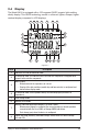
4. SET-UP
Turn the rotary switch to the SET-UP position.
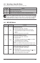
4.1 Menu Items
The SET-UP position gives access to the following options to set user de ned
parameters for instrument con guration:
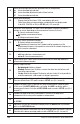
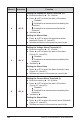
No. Function
1 Erases stored measurements.
2 Enables/disables the buzzer.
3 Enables/disables Auto Power OFF
4 Sets the impedance alarm threshold (W).
5 Sets the voltage alarm threshold (V).
6 Sets the current alarm threshold (I).
7 Sets the date.
8 Sets the time.
9 Selects the Standard or Advanced operating mode.
10 Selects the test frequency for the impedance.
11 Enables/disables the AUTO-HOLD mode.
12 Displays the version number.
13 Not used.
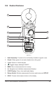
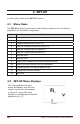
4.2 SET-UP Menu Displays
The 12 accessible menus are
clearly identi ed by their title and
number, as shown in the example
in Figure 4-1 (menu #5) which
displays the voltage alarm threshold
adjustment (AL. V).